
Theory and Design for Mechanical Measurements
6th Edition
ISBN: 9781118881279
Author: Richard S. Figliola, Donald E. Beasley
Publisher: WILEY
expand_more
expand_more
format_list_bulleted
Videos
Textbook Question
Chapter 8, Problem 8.35P
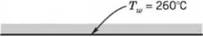
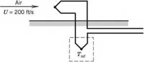

Figure 8.48 Schematic diagram for Problems 8.33, 34, and 35.
8.35 An iron-constantan thermocouple is placed in a moving air stream in a duct, as shown in Figure 8.48. The air flows at 180 ft/sec. The emissivity of the thermocouple is 0.7 and the recovery factor is 0.7. The wall temperature, Twis 500 °F. The thermocouple reference junction is maintained at 32 °F. The emf output from the thermocouple is 20 mV.
- Determine the thermocouple junction temperature.
- By considering recovery and radiation errors, estimate the possible value for total error in the indicated temperature. Discuss whether this estimate of the measurement error is conservative and why, or why not. The heat-transfer coefficient may be taken as 40 Btu/hr-ft °F, and the specific heat as cp= 0.24 Btu/lbm°F.
Expert Solution & Answer
Want to see the full answer?
Check out a sample textbook solution
Students have asked these similar questions
6. A Thomas meter is located in an air duct of 2 sq ft cross-sectional area.
The air weighs 0.083 lb per cu ft, and its specific heat is 0.24. Assume
a controlled temperature differential of 5° and heater potential of 110
volts. Plot the velocity as abscissa and amperage as ordinate for veloc-
ity 0 to 300 ft per min. Assume constant amperage of 3, and plot tem-
perature difference against velocity. Discuss the curves from the stand-
point of accuracy of the system.
J: よ
itet
legeted
oulindriool oir tube
a. An air stream passing through a 2-inch (1/6 ft) diameter, thin-walled tube is to be heated by high-
pressure steam condensing on the outer surface of the tube at 320 °F. The overall heat transfer
coefficient, h between steam and air can be assumed to be 25 Btu/(ft2.hr °F) with the air entering
at 100 ft/sec, 10 psia, 40 °F. The air is to be heated to 150 °F. Determine the tube length required.
Assuming Rayleigh Line flow, calculate the static pressure change due to heat addition.
Also, for the same inlet conditions, calculate the pressure drop due to friction, assuming Fanno
flow in the duct with f = 0.018.
b.
c.
d.
To obtain an approximation to the overall pressure drop in this heat exchanger, add the two
results. Discuss the accuracy of this calculation.
An air-cooled condenser has an expected U value of 30 based on the air-side area. The
m²-k
condenser is to transfer 60 kW with an airflow rate of 15 kg/s entering at 35°C. If the condensing
temperature is to be 48°C, what is the required air-side area? Recall Cp,air = 1.0-
kg-K
kJ
Chapter 8 Solutions
Theory and Design for Mechanical Measurements
Ch. 8 - Prob. 8.1PCh. 8 - Fixed temperature points in the International...Ch. 8 - Answers to the following questions may be found in...Ch. 8 - Calculate the resistance of a platinum wire that...Ch. 8 - Plot the resistance of a platinum wire that is 5 m...Ch. 8 - An RTD forms one arm of a Wheatstone bridge, as...Ch. 8 - An RTD forms one arm (/?4) of a Wheatstone bridge,...Ch. 8 - Research and describe current state-of-the-art...Ch. 8 - Prob. 8.9PCh. 8 - 8.10 Estimate the required level of uncertainty in...
Ch. 8 - 8.11 A thermistor is placed in a 100 °C...Ch. 8 - Prob. 8.12PCh. 8 - Prob. 8.13PCh. 8 - The thermocouple circuit in Figure 8.45 represents...Ch. 8 - The thermocouple circuit in Figure 8.45 represents...Ch. 8 - The thermocouple circuit in Figure 8.45 is...Ch. 8 - 8.17 a. The thermocouple shown in Figure 8.46a...Ch. 8 - Prob. 8.18PCh. 8 - Prob. 8.19PCh. 8 - A temperature measurement requires an uncertainty...Ch. 8 - A temperature difference of 3.0 °C is measured...Ch. 8 - Complete the following table for a J-type...Ch. 8 - Complete the following table for a T-type...Ch. 8 - Prob. 8.24PCh. 8 - 8.25 You are employed as a heating, ventilating,...Ch. 8 - A J-type thermocouple for use at temperatures...Ch. 8 - A J-type thermocouple is calibrated against an RTD...Ch. 8 - A beaded thermocouple is placed in a duct in a...Ch. 8 - Consider a welded thermocouple bead that...Ch. 8 - Prob. 8.30PCh. 8 - Prob. 8.31PCh. 8 - Consider the typical construction of a sheathed...Ch. 8 - An iron-constantan thermocouple is placed in a...Ch. 8 - Figure 8.48 Schematic diagram for Problems 8.33,...Ch. 8 - Figure 8.48 Schematic diagram for Problems 8.33,...Ch. 8 - 8.36 In Example 8.5, an uncertainty value for Rf...Ch. 8 - The thermocouple circuit shown in Figure 8.49...Ch. 8 - Prob. 8.38PCh. 8 - 8.39 A thin-film heat flux sensor employs a K-type...Ch. 8 - A thin-film heat flux sensor has a sensitivity uV...Ch. 8 - 8.41 A T-type thermopile is used to measure...Ch. 8 - 8.42 A T-type thermocouple referenced to 0 °C is...Ch. 8 - A T-type thermocouple referenced to 0 °C develops...Ch. 8 - 8.44 A temperature measurement system consists of...
Knowledge Booster


Learn more about
Need a deep-dive on the concept behind this application? Look no further. Learn more about this topic, mechanical-engineering and related others by exploring similar questions and additional content below.Similar questions
- 6- The following reading were taken during a test on a surface condenser: Mean condenser temperature = 35°C Hot well temperature = 30°C Condenser vacuum = 69 cm Hg Barometer reading = 76cmHg Condensation rate = 16 kg/min Cooling water temperature inter = 20 °C Cooling water temperature outlet = 32.5 °C Flow rate being = 37500 kg/h Calculate: a- mass of air present per cubic meter of condenser b- quality of steam at condenser inlet c- vacuum efficiency d- condenser efficiency (condenser heat transfer effeteness)arrow_forwardA concentrating solar collector array with 42 modules each comprising a CLFR (refer to Figure 8.11) and an absorber tube is used for raising steam under the following operating conditions:• Superheated steam condition: p1 = 100 bars, t1 = 550°C, enthalpy h1 = 3500 kJ/kg (from h,s-diagram)• Feedwater temperature is t2 = 268°C and its enthalpy is h2 = cp t2 = 4.187 × 268 = 1122 kJ/kg• Direct (beam) normal insolation (DNI) at the system location Ib,N = 833 W/m2 • Aperture area of a single CLFR module Aap = 390 m2• Efficiency of the solar collector ηc = 0.71 Calculate (i) the rate of useful heat output of the CLFR array and (ii) therate of steam production.arrow_forward28. The measurement of a thermocouple can be found directly from its standard data table if the reference temperature used by the thermocouple is not 0°C. (a) True (b) Falsearrow_forward
- The following data were obtained from a test of a surface condenser: Inlet temperature of circulating water = 21°C Outlet temperature of circulating water = 35°C Vacuum in the condenser mm of Hg Compute the efficiency of the condenser. 704.7 mm of Hg Barometer reading 760arrow_forwardA surface condenser is designed to handle 10000 kg of steam per hour. The steam enters at 0.08 bar abs. and 0.9 dryness and the condensate leaves at the corresponding saturation temperature. The pressure is constant throughout the condenser. Estimate the cooling water flow per hour, If the cooling water temperature rise is limited to 10 degrees * C|arrow_forwardThe figure 1 above presents a crudely simplified centralised water heating system. The system comprises of two heating lines, the first line having one radiatorand the second has four radiators in series.The pressure after the pump (point (1)) is 2 bar, and the flow velocity is 1.2 m/s. For simplicity we can assume the water to be in constant temperature of 60◦C. Loss coefficients and pressure losses are listed in Table 1, and pipe lengths and diameters are given in Table 2.For the system balancing, the target is to divide the mass flow so, so that 20% of the mass flow goes to the first line (i.e. through radiator R1.1) and 80% of the flow goes to the second line (R2.1 - R2.4):(a) How large pressure loss is needed in the control valve CV1 to get the desired flow rates in the two lines? (b) How large is then the minor loss coefficient of the said valve, KCV1? (c) How much is the pressure, in bar, at the end of the line at section 4?arrow_forward
- . A simple air cooled system is used for an aeroplane to take a load of 10 tons. Atmospheric temperature and pressure is 25°C and 0.9 atm respectively. Due to ramming the pressure of air is increased from 0.9 atm, to 1 atm. The pressure of air leaving the main compressor is 3.5 atm and its 50% heat is removed in the air-cooled heat exchanger and then it is passed through a evaporator for future cooling. The temperature of air is reduced by 10°C in the evaporator. Lastly the air is passed through cooling turbine and is supplied to the cooling cabin where the pressure is 1.03 atm. Assuming isentropic efficiency of the compressor and turbine are 75% and 70%, finda) Power required to take the load in the cooling cabinb) COP of the system.The temperature of air leaving the cabin should not exceed 25°C.arrow_forwardA vertical-tube two-pass heater is used for heating gas oil. Saturated steam at 100 lbf/in^2 gauge is used as a heating medium. The tubes are 1 in. OD by BWG 16 and are made of mild steel. The oil enters at 60°F and leaves at 150°F. The viscosity-temperature relation is exponential. The viscosity at 60°F is 5.0 cP and at 150°F is 1.8 cP. The oil is 37° API (specific gravity 0.840) at 60°F. The flow of oil is 150 bbl/h (1 bbl = 42 gal). Assume the steam condenses in film condensation. The thermal conductivity of the oil is 0.078 Btu/ft-h-°F, and the specific heat is 0.480 Btu/1b-°F. The velocity of the oil in the tubes should be approximately 4 ft/s. Calculate the length of tubes needed for this heater.arrow_forward7. A 6 in. x 20 ft uninsulated pipe schedule 80 conveys steam at 385°F with an average ambient temperature of 85°F. If the cost of the fuel is Php. 240.00 per 106 Btu with the net energy conversion efficiency of 78%, what is the annual cost of the heat lost? Note: For 6" pipe scheduled 80: Do = 6.625 in.; Di = 5.761 in. For iron: k = 30 Btu/hr-ft-°F For the surface coefficients: hi = 1000 Btu/hr-ft²-°F; ho = 2 Btu/hr-ft²-°Farrow_forward
- Example 2: The following data apply to an air-conditioning system RSH=11.6 kW RLH=11.6 Kw In side condition 25°C & RH=50% & outside condition 35°C DBT & 27.8°C WBT Return air from the room is mixed with the outside air before entering the cooling coil a ratio 4:1 Return air from the room is mixed with the air leaving the cooling coil at a ratio 1:4, cooling coil by pass factor =0.1. The air may be reheated if necessary before suppling the condition, assume tdp=10°C. find 1- Supply air condition to the room 2- Refrigeration load (Colling coil load) 3- Total refrigeration capacity d- The quantity of fresh air suppliedarrow_forward1. 400,000 Ibm/hr of 270°F water is to be heated to 370°F by condensing saturated 390°F steam. (The steam does not sub cool upon condensing). Your job is to design the heat exchanger. The following parameters represent constraint your design. number of tube passes 4 tube fluid water being heated number of shell pass shell fluid steam being cooled U (based on outside tube area) 700 BTU/hr – ft² – °F 1 in tube outside diameter tube wall thickness 1/16 in bulk tube fluid velocity 5 ft/s (a) How many tubes are required per pass? (b) How many tubes are required total? (c) Allowing 3 ft for headers and flanges, how long should the exchanger be?arrow_forwardCatalogue data of a water-cooled condenser of a manufacturer gives the following details: Condensing temperature 48.9°C Water inlet temperature 37.8°C Water flow rate 20.694 kg/s Capacity 145 tons Estimate the capacity of this condenser with the same water flow rate but with an inlet temperature of 30°C and a condensation temperature of 42°C. The evaporation temperature may be assumed to be constant at 2.2°C.arrow_forward
arrow_back_ios
SEE MORE QUESTIONS
arrow_forward_ios
Recommended textbooks for you
 Elements Of ElectromagneticsMechanical EngineeringISBN:9780190698614Author:Sadiku, Matthew N. O.Publisher:Oxford University Press
 Mechanics of Materials (10th Edition)Mechanical EngineeringISBN:9780134319650Author:Russell C. HibbelerPublisher:PEARSON
 Thermodynamics: An Engineering ApproachMechanical EngineeringISBN:9781259822674Author:Yunus A. Cengel Dr., Michael A. BolesPublisher:McGraw-Hill Education
 Control Systems EngineeringMechanical EngineeringISBN:9781118170519Author:Norman S. NisePublisher:WILEY
 Mechanics of Materials (MindTap Course List)Mechanical EngineeringISBN:9781337093347Author:Barry J. Goodno, James M. GerePublisher:Cengage Learning
 Engineering Mechanics: StaticsMechanical EngineeringISBN:9781118807330Author:James L. Meriam, L. G. Kraige, J. N. BoltonPublisher:WILEY
Elements Of Electromagnetics
Mechanical Engineering
ISBN:9780190698614
Author:Sadiku, Matthew N. O.
Publisher:Oxford University Press
Mechanics of Materials (10th Edition)
Mechanical Engineering
ISBN:9780134319650
Author:Russell C. Hibbeler
Publisher:PEARSON
Thermodynamics: An Engineering Approach
Mechanical Engineering
ISBN:9781259822674
Author:Yunus A. Cengel Dr., Michael A. Boles
Publisher:McGraw-Hill Education
Control Systems Engineering
Mechanical Engineering
ISBN:9781118170519
Author:Norman S. Nise
Publisher:WILEY
Mechanics of Materials (MindTap Course List)
Mechanical Engineering
ISBN:9781337093347
Author:Barry J. Goodno, James M. Gere
Publisher:Cengage Learning
Engineering Mechanics: Statics
Mechanical Engineering
ISBN:9781118807330
Author:James L. Meriam, L. G. Kraige, J. N. Bolton
Publisher:WILEY
Extent of Reaction; Author: LearnChemE;https://www.youtube.com/watch?v=__stMf3OLP4;License: Standard Youtube License