
Theory and Design for Mechanical Measurements
6th Edition
ISBN: 9781118881279
Author: Richard S. Figliola, Donald E. Beasley
Publisher: WILEY
expand_more
expand_more
format_list_bulleted
Videos
Textbook Question
Chapter 8, Problem 8.33P
An iron-constantan thermocouple is placed in a moving air stream in a duct, as shown in Figure 8.48. The thermocouple reference junction is maintained at 212 °F. The wall temperature, Tw>is 500 °F, and the air velocity is 200 ft/s. The output voltage from the thermocouple is 14.143 mV.
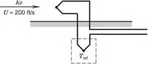

Figure 8.48 Schematic diagram for Problems 8.33, 34, and 35.
- Determine the thermocouple junction temperature.
- By considering recovery and radiation errors, estimate the possible value for total error in the indicated temperature. Discuss whether this estimate of the measurement error is conservative and why, or why not. The heat-transfer coefficient may be taken as 70 Btu/hr-ff-°F.
| Air Properties | Thermocouple Properties |
| Cp = 0.24 Btu/lbm°F | r = 0.7 |
| U = 200 ft/s | e = 0.25 |
Expert Solution & Answer
Want to see the full answer?
Check out a sample textbook solution
Students have asked these similar questions
6. A Thomas meter is located in an air duct of 2 sq ft cross-sectional area.
The air weighs 0.083 lb per cu ft, and its specific heat is 0.24. Assume
a controlled temperature differential of 5° and heater potential of 110
volts. Plot the velocity as abscissa and amperage as ordinate for veloc-
ity 0 to 300 ft per min. Assume constant amperage of 3, and plot tem-
perature difference against velocity. Discuss the curves from the stand-
point of accuracy of the system.
J: よ
itet
legeted
oulindriool oir tube
1. Figure 1 below shows a stirred tank heating process-with a constant holdup volume.
Assume mass flow rate w, of the inlet pipe is constant whereas its temperature T
fluctuates but the product temperature T must be maintained within set temperature
tolerances about the reference.
Heater
Figure 1: Stirred heating tank process
a. An air stream passing through a 2-inch (1/6 ft) diameter, thin-walled tube is to be heated by high-
pressure steam condensing on the outer surface of the tube at 320 °F. The overall heat transfer
coefficient, h between steam and air can be assumed to be 25 Btu/(ft2.hr °F) with the air entering
at 100 ft/sec, 10 psia, 40 °F. The air is to be heated to 150 °F. Determine the tube length required.
Assuming Rayleigh Line flow, calculate the static pressure change due to heat addition.
Also, for the same inlet conditions, calculate the pressure drop due to friction, assuming Fanno
flow in the duct with f = 0.018.
b.
c.
d.
To obtain an approximation to the overall pressure drop in this heat exchanger, add the two
results. Discuss the accuracy of this calculation.
Chapter 8 Solutions
Theory and Design for Mechanical Measurements
Ch. 8 - Prob. 8.1PCh. 8 - Fixed temperature points in the International...Ch. 8 - Answers to the following questions may be found in...Ch. 8 - Calculate the resistance of a platinum wire that...Ch. 8 - Plot the resistance of a platinum wire that is 5 m...Ch. 8 - An RTD forms one arm of a Wheatstone bridge, as...Ch. 8 - An RTD forms one arm (/?4) of a Wheatstone bridge,...Ch. 8 - Research and describe current state-of-the-art...Ch. 8 - Prob. 8.9PCh. 8 - 8.10 Estimate the required level of uncertainty in...
Ch. 8 - 8.11 A thermistor is placed in a 100 °C...Ch. 8 - Prob. 8.12PCh. 8 - Prob. 8.13PCh. 8 - The thermocouple circuit in Figure 8.45 represents...Ch. 8 - The thermocouple circuit in Figure 8.45 represents...Ch. 8 - The thermocouple circuit in Figure 8.45 is...Ch. 8 - 8.17 a. The thermocouple shown in Figure 8.46a...Ch. 8 - Prob. 8.18PCh. 8 - Prob. 8.19PCh. 8 - A temperature measurement requires an uncertainty...Ch. 8 - A temperature difference of 3.0 °C is measured...Ch. 8 - Complete the following table for a J-type...Ch. 8 - Complete the following table for a T-type...Ch. 8 - Prob. 8.24PCh. 8 - 8.25 You are employed as a heating, ventilating,...Ch. 8 - A J-type thermocouple for use at temperatures...Ch. 8 - A J-type thermocouple is calibrated against an RTD...Ch. 8 - A beaded thermocouple is placed in a duct in a...Ch. 8 - Consider a welded thermocouple bead that...Ch. 8 - Prob. 8.30PCh. 8 - Prob. 8.31PCh. 8 - Consider the typical construction of a sheathed...Ch. 8 - An iron-constantan thermocouple is placed in a...Ch. 8 - Figure 8.48 Schematic diagram for Problems 8.33,...Ch. 8 - Figure 8.48 Schematic diagram for Problems 8.33,...Ch. 8 - 8.36 In Example 8.5, an uncertainty value for Rf...Ch. 8 - The thermocouple circuit shown in Figure 8.49...Ch. 8 - Prob. 8.38PCh. 8 - 8.39 A thin-film heat flux sensor employs a K-type...Ch. 8 - A thin-film heat flux sensor has a sensitivity uV...Ch. 8 - 8.41 A T-type thermopile is used to measure...Ch. 8 - 8.42 A T-type thermocouple referenced to 0 °C is...Ch. 8 - A T-type thermocouple referenced to 0 °C develops...Ch. 8 - 8.44 A temperature measurement system consists of...
Knowledge Booster


Learn more about
Need a deep-dive on the concept behind this application? Look no further. Learn more about this topic, mechanical-engineering and related others by exploring similar questions and additional content below.Similar questions
- m = 5.65 lb/h Twall %3D = 350 F T T. Dpipe=1.5 in h = 3.2 Btu/(lb-F) Cair = 0.24 Btu/(lb-F) L=6 in hc T= 200 F the pipe shown in figure carry air. if the inlet tem outlet temperature at node 2. neglect the conduction part and assume this pipe is one element ure at node 1 is 200 F, determine the 350 F 123 F 275 F 253 Farrow_forwardSubject : Thermofluid Question : Air at 20oC flows in a 0.60 m diameter pipe at a rate of 15 m3/s as shown in Figure 3. The pipe diameter changes to 1.2 m through a sudden expansion. i. Assess the pressure rise across this expansion. ii. Explain how there can be a pressure rise across the expansion when there is an energy loss (KL ≠ 0).arrow_forwardAn air-cooled condenser has an expected U value of 30 based on the air-side area. The m²-k condenser is to transfer 60 kW with an airflow rate of 15 kg/s entering at 35°C. If the condensing temperature is to be 48°C, what is the required air-side area? Recall Cp,air = 1.0- kg-K kJarrow_forward
- 7. A 6 in. x 20 ft uninsulated pipe schedule 80 conveys steam at 385°F with an average ambient temperature of 85°F. If the cost of the fuel is Php. 240.00 per 106 Btu with the net energy conversion efficiency of 78%, what is the annual cost of the heat lost? Note: For 6" pipe scheduled 80: Do = 6.625 in.; Di = 5.761 in. For iron: k = 30 Btu/hr-ft-°F For the surface coefficients: hi = 1000 Btu/hr-ft²-°F; ho = 2 Btu/hr-ft²-°Farrow_forwardA concentrating solar collector array with 42 modules each comprising a CLFR (refer to Figure 8.11) and an absorber tube is used for raising steam under the following operating conditions:• Superheated steam condition: p1 = 100 bars, t1 = 550°C, enthalpy h1 = 3500 kJ/kg (from h,s-diagram)• Feedwater temperature is t2 = 268°C and its enthalpy is h2 = cp t2 = 4.187 × 268 = 1122 kJ/kg• Direct (beam) normal insolation (DNI) at the system location Ib,N = 833 W/m2 • Aperture area of a single CLFR module Aap = 390 m2• Efficiency of the solar collector ηc = 0.71 Calculate (i) the rate of useful heat output of the CLFR array and (ii) therate of steam production.arrow_forward3. A 6 in x 20 ft uninsulated B.I pipe conveys steam at 385 °F with an average ambient temperature of 85°F. if the cost of the fuel is PhP 250.00 per 106 BTU with the net energy conversion efficiency of 75%, what is the annual cost of the heat lost? For 6 in. pipe schedule 80:Do = 6.625 inDi = 5.761 in For iron:k = 30 BTU/ hr ft °F for the surface coefficients:hi = 1000BTU/ hr ft2°F ho = 2 BTU/hr ft2 °Farrow_forward
- 8.7 A point-focus concentrating solar collector comprising a heliostat field and central receiver and a steam turbine-generator unit (refer to Figure 8.8) is operating under the following conditions: • Power plant electric power output Pa = 75 MW • Single heliostat surface area A, = 125 m? • Beam solar radiation flux incident on the heliostat IN = 835 W/m? • Heliostat-receiver concentration ratio C = 510 Efficiency of solar collector, that is, heliostat field and central receiver n = 0.69 • Efficiency of the power plant cycle and turbine-generator unit Nng = 0.36 • HTF in the receiver: molten salt (sodium potassium nitrates) with spe- cific heat e of 1.03 kJ/(kg K) • HTF temperature rises in the absorber/receiver from 298°C to 563°C, that is, AT, = 265 K Calculate (i) the overall (electrical) efficiency of the power plant, (ii) the rate of useful heat output of the central receiver/absorber, (iii) the total reflecting surface area of the heliostat field, (iv) the number of heliostats…arrow_forward1- For the following design conditions:- Condenser heat load (Qc) = 293 MW Condenser Pressure (Pcond) = 0.06 bar Cooling Water inlet temperature (tw,) = 25 C° Cooling Water velocity (Vw) = 2 m/s Number of Passes (N) = Single Tube Diameter (D) Tube Length (L) = 15 m Tubes Cleanliness factor (Fclean) = 0.85 Overall heat transfer coefficient (U,) = 4000 W /m²C°. Calculate the following:- = 25 mm a. Condenser Surface area b. Cooling water mass flow rate c. Condenser effectivenessarrow_forwardUse appropriate diagram and sketches. When the cold junction of a thermocouple thermometer is at 0° C and the hot junction at 100°C the millivoltmeter shows a deflection of 4.2 mV towards the left. The cold junction is now put in an unknown temperature while maintaining the hot junction at 100°C. The millivoltmeter now shows a deflection of 5.2 mV towards the right. Calculate the unknown temperaturearrow_forward
- Question B2 - Internal Flow In a large student house in Sheffield, cold water is supplied by the mains water supply at a pressure of 2 bar, gauge, and at a temperature 10°C. A wash basin cold tap is located 3 meters above the mains supply, connected to the mains pipe with a copper pipe of internal diameter 15 mm and length 12 meters. When the tap is opened the flow rate of water out of the tap is 24 litres per minute, creating a Fanning friction factor in the pipe of 0.008. a) Calculate the Reynolds number of the water in the pipe and determine if it is laminar or turbulent. b) Calculate the pressure loss from friction, change in elevation, and hence the pressure of the water just before entering the tap. c) to part b) and state if these assumptions under or over predict the pressure of the water just before entering the tap. Name two assumptions that have been made in order to arrive at your answerarrow_forwardQuestion B2 - Internal Flow In a large student house in Sheffield, cold water is supplied by the mains water supply at a pressure of 2 bar, gauge, and at a temperature 10°C. A wash basin cold tap is located 3 meters above the mains supply, connected to the mains pipe with a copper pipe of internal diameter 15 mm and length 12 meters. When the tap is opened the flow rate of water out of the tap is 24 litres per minute, creating a Fanning friction factor in the pipe of 0.008. d) If the value were not given, what procedure would be needed to determine the Fanning friction factor?arrow_forwardThe temperatures of the 20 ºC 25 ºC 30 ºC water at outlet Task 1 Explain the system parameters using the Non- Flow Energy Equationarrow_forward
arrow_back_ios
SEE MORE QUESTIONS
arrow_forward_ios
Recommended textbooks for you
 Elements Of ElectromagneticsMechanical EngineeringISBN:9780190698614Author:Sadiku, Matthew N. O.Publisher:Oxford University Press
 Mechanics of Materials (10th Edition)Mechanical EngineeringISBN:9780134319650Author:Russell C. HibbelerPublisher:PEARSON
 Thermodynamics: An Engineering ApproachMechanical EngineeringISBN:9781259822674Author:Yunus A. Cengel Dr., Michael A. BolesPublisher:McGraw-Hill Education
 Control Systems EngineeringMechanical EngineeringISBN:9781118170519Author:Norman S. NisePublisher:WILEY
 Mechanics of Materials (MindTap Course List)Mechanical EngineeringISBN:9781337093347Author:Barry J. Goodno, James M. GerePublisher:Cengage Learning
 Engineering Mechanics: StaticsMechanical EngineeringISBN:9781118807330Author:James L. Meriam, L. G. Kraige, J. N. BoltonPublisher:WILEY
Elements Of Electromagnetics
Mechanical Engineering
ISBN:9780190698614
Author:Sadiku, Matthew N. O.
Publisher:Oxford University Press
Mechanics of Materials (10th Edition)
Mechanical Engineering
ISBN:9780134319650
Author:Russell C. Hibbeler
Publisher:PEARSON
Thermodynamics: An Engineering Approach
Mechanical Engineering
ISBN:9781259822674
Author:Yunus A. Cengel Dr., Michael A. Boles
Publisher:McGraw-Hill Education
Control Systems Engineering
Mechanical Engineering
ISBN:9781118170519
Author:Norman S. Nise
Publisher:WILEY
Mechanics of Materials (MindTap Course List)
Mechanical Engineering
ISBN:9781337093347
Author:Barry J. Goodno, James M. Gere
Publisher:Cengage Learning
Engineering Mechanics: Statics
Mechanical Engineering
ISBN:9781118807330
Author:James L. Meriam, L. G. Kraige, J. N. Bolton
Publisher:WILEY
Heat Transfer – Conduction, Convection and Radiation; Author: NG Science;https://www.youtube.com/watch?v=Me60Ti0E_rY;License: Standard youtube license