
Concept explainers
Videos
A J-type thermocouple for use at temperatures between 0 and 100 °C was calibrated at the steam point in a device called a hypsometer. A hypsometer creates a constant temperature environment at the saturation temperature of water, at the local barometric pressure. The steam-point temperature is strongly affected by barometric pressure variations. Atmospheric pressure on the day of this calibration was 30.1 in. Hg. The steam-point temperature as a function of barometric pressure may be expressed as
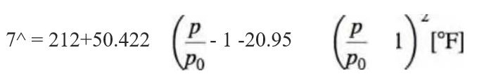
where pQ= 29.921 in. Hg. At the steam point, the output voltage produced by the thermocouple, referenced to 0 °C, is measured as 5.310 mV. Construct a calibration curve for this thermocouple by plotting the difference between the thermocouple reference table value and the measured value (Vref - Vmeas) versus temperature. What is this difference at 0 °C? Suggest a means for measuring temperatures between 0 and 100 °C using this calibration, and estimate the contribution to the total uncertainty.
Want to see the full answer?
Check out a sample textbook solution
Chapter 8 Solutions
Theory and Design for Mechanical Measurements


- 1. To determine the dynamic viscosity of a liquid you take repeated measurements of the liquid density and kinematic viscosity. These data are summarized in the following table: Avg. measurement Total Uncertainty P 999 kg/m³ ±0.5% V 1.23 mm²/s ±0.01 mm²/s kg Ns What is the dynamic viscosity? Give dynamic viscosity in units of; which is the same as ms 2. Determine the absolute and relative uncertainties in the dynamic viscosity.arrow_forwardA thermocouple is used to measure the temperature T1. The thermocouple reference junction labeled 2 is at a temperature of 20°C. The voltage output is measured using a potentiometer and found to be 4.686 mV. What is T1 in degrees RK: if the temperature values are not in the table, you have to use interpolation. Select one: O a. 98 O b. 118 O c. 105 O d. 108 Previous page Next pagearrow_forwardWhat should be the surface tension of a liquid if its density, which is 1.44 g/cc, is the same as that of the calibrating liquid? The displacements of the liquid and the calibrating liquid inside the capillary tube are both 0.5 cm. The surface tension of the calibrating liquid is 29.4509 dynes/cm.arrow_forward
- A thermometer having a time constant of 0.2 min is placed in a temperature bath, and after the thermometer comes to equilibrium with the bath, the temperature of the bath is increased linearly with time at a rate of l0 C/min. What is the difference between the indicated temperature and the bath temperature (a) 0.1 min, (b) 1.0 min after the change in temperature begins?arrow_forwardis a measure of the amount by which a fluid offers a resistance to compression 2. Air contained in a tank is under an absolute pressure of 60 kPa and has a temperature of 60 C. The mass of the air in the tank = 3. Viscosity is a property of a fluid that measures the of a very thin layer of fluid over an adjacent one. 4. When the liquid pressure is dropped below the vapor pressure due to a flow phenomenan, the process is called S. The atmospheric pressure can be measured using a simple device called 6. is an electromechanical device that performs a digital readout. is a non-dimensional quantity to determine the flow type related to its frictional effectarrow_forwardSelect two saturated and two unsaturated samples of air from the dataset of pressure and temperature given below: Pressure (mb): 10, 20, 30 Temperature (°C): 10, 20, 30 Let A and B be two air samples, where A: (T=30°C, P=25 mb) and B: (T=30°C, P=30 mb). For each sample, determine the following: a. Saturation vapor pressure b. Dew point c. Relative humidity d. If samples A and B were cooled to 15°C. What would be their relative humidity? What would be their dew point temperature?arrow_forward
- Physical Applications of 1st Order DE At 1:00 p.m., a thermometer reading 70 0F is taken outside where the air temperature is -10 0F (ten below zero). At 1:02 p.m., the reading is 26 0 At 1:05 p.m., the thermometer is taken back indoors where the air is at 70 0F. What is the thermometer reading at 1:09 p.m.?arrow_forward7) Give two disadvantages of empirical thermometers. 8) Consider two liquids, A and B. with temperatures Te > TA. The two objects are put into thermal contact for a time period. Without just saying 'heat flows from hot to cold' how would you prove to someone that a quantity of heat flowed from B to A. (think of James Joule's experiments) 9) If the temperature of the sun were to suddenly double, by what multiplicative factor would the thermal radiation change ? Show Workarrow_forwardQ.1 a. Repeatability and reproducibility are ways of measuring precision, particularly in the field of engineering. i. What is an engineer's expectation when performing repeatability or reproducibility? ii. State a difference between repeatability and reproducibility in an experiment? b. Figure Q.1 shows the measurement data of two types of thermal transducers namely thermocouple. Турe E Туре К 6.8 4.2 20 40 60 80 100 Temperature Difference (°C) Voltage Output (mV)arrow_forward
- At a pressure of 0.01 atm, determine (a) the melting temperature for ice, and (b) the boiling temperature for water. You might want to use Animated Figure. (a) i °C (b) і °Carrow_forward4- A thermometer having a time constant of 0.4 min. is placed in a temperature bath and after the thermometer comes to equilibrium with the bath, the temperature of the bath is increased linearly with time at the rate of 2 deg.C min. what is the difference between the indicated temperature and bath temperature after : (a) 2 min. (b) 20 min.arrow_forwardThe graph below shows the pressure and volume for a sample of dry air carried out at two different constant temperatures. Volume (x 10-³ m ³) 2.5 N 1.5 1 0.5 0 50 M 100 150 Pressure (k Pa) 200 250 -T= 300 K -T200 K An isothermal change has to be carried out very slowly. Explain why this is the case. Use data from the graph and the ideal gas equation to calculate the number of moles of gas in the sample.arrow_forward
 Principles of Heat Transfer (Activate Learning wi...Mechanical EngineeringISBN:9781305387102Author:Kreith, Frank; Manglik, Raj M.Publisher:Cengage Learning