
Concept explainers
Videos
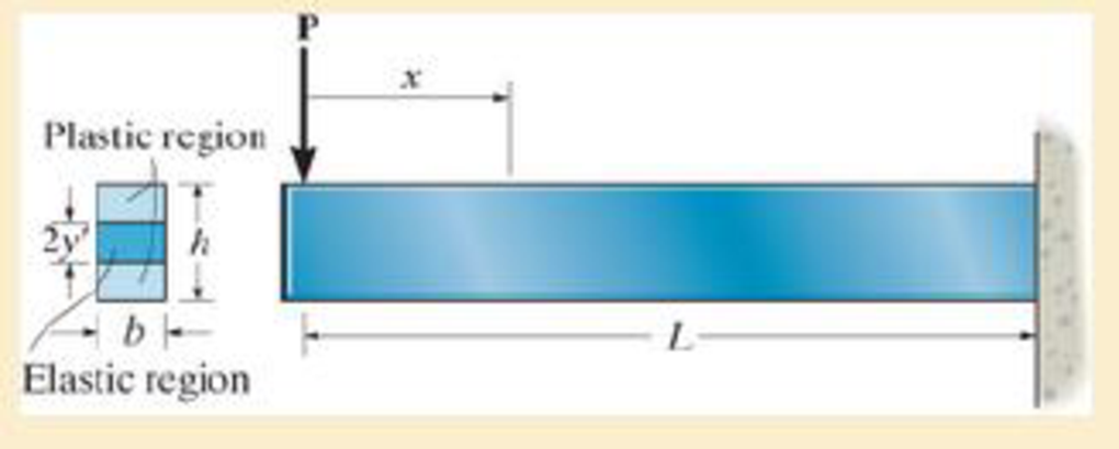
The beam has a rectangular cross section and is subjected to a load P that is just large enough to develop a fully plastic moment Mp = PL at the fixed support. If the material is elastic perfectly plastic, then at a distance x < L the moment M = Px creates a region of plastic yielding with an associated elastic core having a height 2y'. This situation has been described by Eq.6–30 and the moment M is distributed over the cross section as shown in Fig.63–48e. Prove that the maximum shear stress in the beam is given by
Prob. 7–30
Want to see the full answer?
Check out a sample textbook solution
Chapter 7 Solutions
Mechanics of Materials


- Find expressions for shear force V and moment M at x = L/2 of beam BC. Express V and M in term s of peak load intensity q0and be a m length variable L.arrow_forwardIf F = 69 N, determine the internal normal force, shear force, and moment at points D and E in the two members. (Figure 1) Figure A D 30⁰° 1 m 0.75 m 2 m B 0.75 m 60% E < 1 of 1 Farrow_forwardDetermine the internal normal force and shear force, and the bending moment in the beam at points C and D. Assume the support at B is a roller. Point C is located just to the right of the 8-kip load. For your explanation section, complete a FBD of the other side of the beam from the version you did to solve the problem. 8 kip 40 kip · ft A to to D B- 8 ft 8 ft- -8 ftarrow_forward
- The frame is pinned at A and supportd by rollers at D. Find the internal normal, internal shear, and bending moment at points E and F. T 2 ft A D E F -2.5 ft 2.5 ft B 1500 lb 5 ft Carrow_forward3 For the beam shown, find the reactions at the supports and plot the shear-force and bending-moment diagrams. V = 9 kN, V2 = 9 kN, V3 = 200 mm, and V4 = 1100 mm. ATAT-V3 Provide values at all key points shown in the given shear-force and bending-moment diagrams. X (mm) B A = B = C = D = E= F= P = Q = E * KN * KN * KN × KN KN x KN ✩ kN.mm *kN.mm D 0.00 Reaction force R₁ (left) = In the shear-force and bending-moment diagrams given, +V 0.00 X (mm) 6.3 kN and reaction force R2 (right) = P 11.7 kN. Q 0.00arrow_forwardTake P = 7 kN. Assume the reactions at the supports A and B are vertical. P 3 kN/m 0.5 m 0.5 m C -1.5 m D 1.5 m- B Determine the magnitude of the resultant internal normal force, Shear force and Bending moment on the cross section through point Darrow_forward
- Q3: The wooden section of the beam is reinforced with two steel plates as shown. If the beam is subjected to a moment of M = 5.0 kN. m, determine the maximum bending 20 mm 300 mm stresses in the steel and wood. Sketch the M = 5 kN-m stress distribution over the cross section. Take 20 mm Ew = 11 GPa and Est = 200 GPa 200 mmarrow_forwardA box is produced by joining the wooden and plywood rectangular elements with screws as shown in the section. The shear force that each screw used in the cross section joint can safely carry is V = 2 kN. If the beam element created in this way is loaded from the middle of the span with a load of P = 100 kN, find the screw gap a and the total number of screws to be used in the beam element. (Cross-section dimensions t = 15mm, b = 150mm, c = 30mm, h = 180mm; beam support span L = 5m)arrow_forwardDraw the shear and moment diagram and find the flexure stress if b = 400 mm and h = 300 mm. R₁ 4m 40 kN/m 4 m 40 KN 20 kN/m 4 m R₂arrow_forward
- The cantilever beam is supported by a fixed support at A, and subjected to the force F = 600 lb and the couple M = 2810 ft-lb. Draw the shear force and bending moment diagrams (in your homework documentation) and determine the equations for V(x) and M(r). Take a = 0 at point A. a •b C M A- В Values for dimensions on the figure are given in the following table. Note the figure may not be to scale. Variable Value a 5.2 ft b 3.9 ft Support Reactions The force reaction at A is Ib (take up as positive). The couple moment reaction at A is ft-lb (take counterclockwise as positive). Shear Force and Bending Moment Equations In section AB: V(x)- In section BC: V(x)- lb and M(x)= ft-lb. lb and 'M(x)= ft-lb.arrow_forwarddetermine the diagram of the shear forces and bending moments in the beam shown below. Data P = 20kN, M = 60kNm, q = 10kN / m, a = 5m, b = 2m, c = 3, alpha = 60.arrow_forwardThe Figure shows a loading set up similar to that of the 'Bending in Beams' laboratory experiment. E = 200 GNm-2 and I = 2 x 10⁻⁹ m4. The bending moment and the radius of curvature at any point in the beam between the support points B and Care respectively: 1 kN 1 kN B A l0.125 m 1.25 m O a. (-)12.5 kNm, 2.8 m O b.(-)125 Nm, 3.2 m OC (-)2.5 kNm, 2.4 m O d.(-)125 Nm, 1.2 marrow_forward
 Mechanics of Materials (MindTap Course List)Mechanical EngineeringISBN:9781337093347Author:Barry J. Goodno, James M. GerePublisher:Cengage Learning