
Mechanics of Materials
11th Edition
ISBN: 9780137605460
Author: Russell C. Hibbeler
Publisher: Pearson Education (US)
expand_more
expand_more
format_list_bulleted
Videos
Textbook Question
Chapter 7.5, Problem 59P
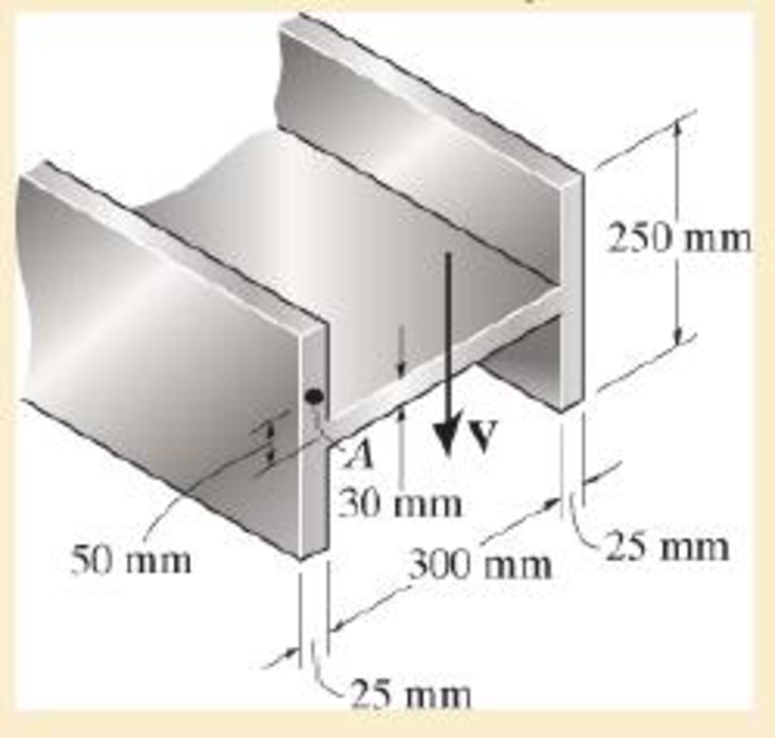
The H-beam is subjected to a shear of V=80 kN Sketch the shear-stress distribution acting along one of its side segments Indicate all peak values
Probs. 7–58/59
Expert Solution & Answer
Want to see the full answer?
Check out a sample textbook solution
Students have asked these similar questions
Determine the equations of bending moment and shear force for 0
1.
Neglecting transverse shear effect show the maximum moments and
determine omax = (16/nD³)(MB + M + M ).
B
P
AB=L
Z.
BC-L
uniform
diameter D
Determine the stress distribution of the beam in cross section A-B when its dimensions are a = 4.0 m, b = 0.5 m, c = 124 mm, and d = 100 mm. The magnitude of the force P is 35 kN.
How much are in cross section A-B
normal force
shear force
bending moment
normal stress at the top of the beam
normal stress at the lower surface of the beam
maximum shear stress
shear stress at y = 62 mm from the lower level
Chapter 7 Solutions
Mechanics of Materials
Ch. 7.2 - If the beam is subjected to a shear force of V =...Ch. 7.2 - Determine the shear stress at points A and B if...Ch. 7.2 - Determine the absolute maximum shear stress in the...Ch. 7.2 - If the beam is subjected to a shear force of V =20...Ch. 7.2 - If the beam is made from four plates and subjected...Ch. 7.2 - If the wide-flange beam is subjected to a shear of...Ch. 7.2 - If the wide-flange beam is subjected to a shear of...Ch. 7.2 - If the wide-flange beam is subjected to a shear of...Ch. 7.2 - The wood beam has an allowable shear stress of...Ch. 7.2 - The shaft is supported by a thrust bearing at A...
Ch. 7.2 - The shaft is supported by a thrust bearing at A...Ch. 7.2 - Determine the largest shear force V that the...Ch. 7.2 - If the applied shear force V = 18 kip, determine...Ch. 7.2 - The overhang beam is subjected to the uniform...Ch. 7.2 - The beam is made from a polymer and is subjected...Ch. 7.2 - Determine the maximum shear stress in the strut if...Ch. 7.2 - Determine the maximum shear force V that the strut...Ch. 7.2 - If the beam is subjected to a shear of V=15 kN,...Ch. 7.2 - If the wide-flange beam is subjected to a shear of...Ch. 7.2 - If the wide-flange beam is subjected to a shear of...Ch. 7.2 - Determine the length of the cantilevered beam so...Ch. 7.2 - If the beam is made from wood having an allowable...Ch. 7.2 - Determine the shear stress at point B on the web...Ch. 7.2 - Determine the maximum shear stress acting at...Ch. 7.2 - The beam is slit longitudinally along both sides....Ch. 7.2 - The beam is to be cut longitudinally along both...Ch. 7.2 - The beam has a rectangular cross section and is...Ch. 7.2 - The beam in Fig.6-48f is subjected to a fully...Ch. 7.3 - The two identical boards are bolted together to...Ch. 7.3 - Two identical 20-mm-thick plates are bolted to the...Ch. 7.3 - The boards are bolted together to form the...Ch. 7.3 - The boards are bolted together to form the...Ch. 7.3 - The beam is constructed from three boards. If it...Ch. 7.3 - The beam is constructed from three boards....Ch. 7.3 - Prob. 38PCh. 7.3 - A beam is constructed from three boards bolted...Ch. 7.3 - The T-beam is constructed as shown. If each nail...Ch. 7.3 - The member consists of two plastic channel strips...Ch. 7.3 - The beam is made from four boards nailed together...Ch. 7.3 - The beam is made from three polystyrene strips...Ch. 7.5 - A shear force of V=300 kN is applied to the box...Ch. 7.5 - A shear force of V=450 kN is applied to the box...Ch. 7.5 - A shear force of V = 18 kN is applied to the box...Ch. 7.5 - A shear force of V = 18 kN is applied to the box...Ch. 7.5 - The aluminum strut is 10 mm thick and has the...Ch. 7.5 - The aluminum strut is 10 mm thick and has the...Ch. 7.5 - The beam is subjected to a shear force of V=50...Ch. 7.5 - The beam is subjected to a shear force of V=50...Ch. 7.5 - The H-beam is subjected to a shear of V=80 kN...Ch. 7.5 - The H-beam is subjected to a shear of V=80 kN...Ch. 7.5 - The built-up beam is formed by welding together...Ch. 7.5 - The assembly is subjected to a vertical shear of V...Ch. 7 - The beam is fabricated from four boards nailed...Ch. 7 - The T-beam is subjected to a shear of V = 150 kN....Ch. 7 - The member is subject to a shear force of V = 2...Ch. 7 - Determine the shear stress at points B and C on...Ch. 7 - Determine the maximum shear stress acting at...
Knowledge Booster


Learn more about
Need a deep-dive on the concept behind this application? Look no further. Learn more about this topic, mechanical-engineering and related others by exploring similar questions and additional content below.Similar questions
- A wooden beam is fabricated by bolting together three members as shown. The 8-mm- diameter bolts are spaced at intervals of s= 200 mm along the x axis of the beam. If the internal shear force in the beam is V=7 kN, determine the shear stress in each bolt. 40 mm 40 mm 90 mm 40 mm 300 mmarrow_forwardCalculate the maximum normal and shear stress values for the attached beam at x = 8.5 m. Determine the distribution of the shear stress in the cross-section in the y-axis direction at y=55 mm, y=109.99 mm and y=110.01 from top. The dimensions of the beam are a = 5.5 m, b = 3.0 m and c = 2.5 m, and the cross-sectional dimensions are d = 170 mm and h = 130 mm. The distributed load of the beam has the value q = 3kN / m and the force F = 10kN.arrow_forward6-54. The beam is made from three boards nailed together as shown. If the moment acting on the cross section is M = 600 N - m, determine the maximum bending stress in the beam. Sketch a three-dimensional view of the stress distribution acting over the cross section. 25 mm 150 mm 20 mm 200 mm M - 600N-m 20 mmarrow_forward
- 1. Neglecting transverse shear effect show the maximum moments and determine omax = (16/TD³)(M; + /M + Mệ). P AB-L BC-L uniform diameter Darrow_forwardF7-2 Determine the shear stres at polnts A and B on the beam ift is subjected to a shear force of V = 600 kN Represent the state af stress on a votume element af these potnts 100 mm 100 m 100 m 100 mm 100 m 100 marrow_forwardDetermine the normal stress and shear stress at a point distant from hP from the bottom surface of the depicted cross, also determine the maximum normal stress and maximum shear stress in the cross section. t=10 mm w= 150 mm h=180 mm V= 5 kN M= 3 kN.m hP= 145 mmarrow_forward
- An A-36 steel strap having a thickness of 10 mm and a width of 20 mm is bent into a circular arc of radius r = 10 m. Determine the maximum bending stress in the strap.arrow_forward10-26. A beam is made up of four 50 X 100-mm full-sized Douglas Fir pieces that are glued to a 25 x 500-mm Douglas Fir plywood web, as shown in the figure. Determine the maximum allowable shear and the maximum allowable bending moment that this section can carry if the allowable bending stress is 10 MPa; the allowable shear stress in plywood is 600 KN /m, and the allowable shearing stress in the glued joints is 300 kN/m^2. AIl dimensions in the figure are in mm.arrow_forwardThe wooden section of the beam is reinforced with two steel plates as shown. If the beam is subjected to a moment of M = 30 kN # m, determine the maximum bending stresses in the steel and wood. Sketch the stress distribution over the cross section. Take Ew = 10 GPa and Est = 200 GPa.arrow_forward
- 12am 2cm Determine the maximum and minimum value of 2cm the normal stress caused by the bending moment M,-20NM on the cross-section given in the figure. M=20NM 18cm Draw the normal stress distribution. 2cm 18cmarrow_forward20 mm 20 mm 4. The simply supported beam on the right is built up from three boards by nailing them together as shown. If P = 12 kN, determine the maximum allowable spacing s of the nails to support the load, if each nail can resist a shear force of 1.5 kN. 1 m m B 100 mm 25 mm- 25 mm 200 mm 25 mmarrow_forward*7-16. The beam has a square cross section and is made of wood having an allowable shear stress of Tallow = 1.4 ksi. If it is subjected to a shear of V = 1.5 kip, determine the smallest dimension a of its sides. Problem 7-16 V = 1.5 kiparrow_forward
arrow_back_ios
SEE MORE QUESTIONS
arrow_forward_ios
Recommended textbooks for you
 Elements Of ElectromagneticsMechanical EngineeringISBN:9780190698614Author:Sadiku, Matthew N. O.Publisher:Oxford University Press
 Mechanics of Materials (10th Edition)Mechanical EngineeringISBN:9780134319650Author:Russell C. HibbelerPublisher:PEARSON
 Thermodynamics: An Engineering ApproachMechanical EngineeringISBN:9781259822674Author:Yunus A. Cengel Dr., Michael A. BolesPublisher:McGraw-Hill Education
 Control Systems EngineeringMechanical EngineeringISBN:9781118170519Author:Norman S. NisePublisher:WILEY
 Mechanics of Materials (MindTap Course List)Mechanical EngineeringISBN:9781337093347Author:Barry J. Goodno, James M. GerePublisher:Cengage Learning
 Engineering Mechanics: StaticsMechanical EngineeringISBN:9781118807330Author:James L. Meriam, L. G. Kraige, J. N. BoltonPublisher:WILEY
Elements Of Electromagnetics
Mechanical Engineering
ISBN:9780190698614
Author:Sadiku, Matthew N. O.
Publisher:Oxford University Press
Mechanics of Materials (10th Edition)
Mechanical Engineering
ISBN:9780134319650
Author:Russell C. Hibbeler
Publisher:PEARSON
Thermodynamics: An Engineering Approach
Mechanical Engineering
ISBN:9781259822674
Author:Yunus A. Cengel Dr., Michael A. Boles
Publisher:McGraw-Hill Education
Control Systems Engineering
Mechanical Engineering
ISBN:9781118170519
Author:Norman S. Nise
Publisher:WILEY
Mechanics of Materials (MindTap Course List)
Mechanical Engineering
ISBN:9781337093347
Author:Barry J. Goodno, James M. Gere
Publisher:Cengage Learning
Engineering Mechanics: Statics
Mechanical Engineering
ISBN:9781118807330
Author:James L. Meriam, L. G. Kraige, J. N. Bolton
Publisher:WILEY
Everything About TRANSVERSE SHEAR in 10 Minutes!! - Mechanics of Materials; Author: Less Boring Lectures;https://www.youtube.com/watch?v=4x0E9yvzfCM;License: Standard Youtube License