
Mechanics of Materials (MindTap Course List)
9th Edition
ISBN: 9781337093347
Author: Barry J. Goodno, James M. Gere
Publisher: Cengage Learning
expand_more
expand_more
format_list_bulleted
Videos
Textbook Question
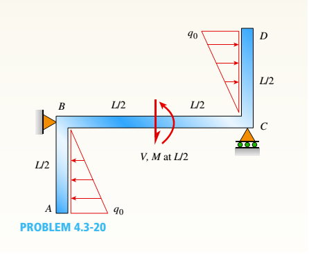
Chapter 4, Problem 4.3.20P
Find expressions for shear force V and moment M at x = L/2 of beam BC. Express V and M in term s of peak load intensity q0and be a m length variable L.
Expert Solution & Answer
Want to see the full answer?
Check out a sample textbook solution
Students have asked these similar questions
For the beam shown, derive the expressions for shear and moment. Show complete solutions. Simplify
all equations. Then draw the shear force and bending moment diagrams below the load diagram.
Draw to scale.
1. Shear and Moment Diagram:
18 kN/m
25 kN-m
A
E
|C
ImIm
- 2 m
3 m·
Shear Equation
Moment Equation
Segment AB
Segment BC
Segment CD
Segment DE
Point of Zero Shear:
Moment at point of zero shear:
The simply supported beam is subjected to the force F = 700 N and the uniform distributed load with
intensity w = 150 N/m. Draw the shear force and bending moment diagrams (in your homework
documentation) and determine the equations for V(r) and M(x). Take a = 0 at point A.
19
F
a
Values for dimensions on the figure are given in the following table. Note the figure may not be to scale.
Variable Value
a
5.2 m
2.6 m
3.12 m
Support Reactions
The reaction at A is
N.
The reaction at D is
N.
Shear Force and Bending Moment Equations
In section AB:
V(x)=
N and M(x)=
N-m.
In section BC:
v(x)-
N and M(x)=
N-m.
In section CD:
V(x)-
N and M(x)=
N-m.
A
3
For the beam shown, find the reactions at the supports and plot the shear-force and bending-moment diagrams. V
= 9 kN, V2 = 9 kN, V3 = 200 mm, and V4 = 1100 mm.
ATAT-V3
Provide values at all key points shown in the given shear-force and bending-moment diagrams.
X
(mm)
B
A =
B =
C =
D =
E=
F=
P =
Q =
E
* KN
* KN
* KN
× KN
KN
x KN
✩ kN.mm
*kN.mm
D
0.00
Reaction force R₁ (left) =
In the shear-force and bending-moment diagrams given,
+V
0.00
X
(mm)
6.3 kN and reaction force R2 (right) =
P
11.7 kN.
Q
0.00
Chapter 4 Solutions
Mechanics of Materials (MindTap Course List)
Ch. 4 - Calculate the shear force V and bending moment...Ch. 4 - Determine the shear force V and bending moment M...Ch. 4 - Determine the shear force V and bending moment M...Ch. 4 - Calculate the shear force V and bending moment M...Ch. 4 - Consider the beam with an overhang shown in the...Ch. 4 - The beam ABC shown in the figure is simply...Ch. 4 - The beam ABCD shown in the figure has overhangs at...Ch. 4 - At a full d raw, an archer applies a pull of 130 N...Ch. 4 - A curved bar ABC is subjected to loads in the form...Ch. 4 - Under cruising conditions, the distributed load...
Ch. 4 - A beam ABCD with a vertical arm CE is supported as...Ch. 4 - A simply supported beam AB supports a trapezoid...Ch. 4 - Beam ABCD represents a reinforced-concrete...Ch. 4 - Find shear (V) and moment (M) at x = 3L/4 for the...Ch. 4 - Find expressions for shear force V and moment M at...Ch. 4 - Find expressions for shear force V and moment Mat...Ch. 4 - Find expressions for shear force V and moment Mat...Ch. 4 - Find expressions for shear force V and moment M at...Ch. 4 - Find expressions for shear force V and moment M at...Ch. 4 - Find expressions for shear force V and moment M at...Ch. 4 - A cable with force P is attached to a frame at A...Ch. 4 - Find expressions for shear force V and moment M at...Ch. 4 - A cable with force P is attached to a frame at D...Ch. 4 - Frame ABCD carries two concentrated loads (2P at T...Ch. 4 - Frame ABC has a moment release just left of joint...Ch. 4 - The simply supported beam ABCD is loaded by a...Ch. 4 - The centrifuge shown in the figure rotates in a...Ch. 4 - Draw the shear-Force and bending-moment diagrams...Ch. 4 - A simple beam AB is subjected to a counter...Ch. 4 - Draw the shear-force and bending-moment diagrams...Ch. 4 - The cantilever beam AB shown in the figure is...Ch. 4 - Cantilever beam AB carries an upward uniform load...Ch. 4 - The simple beam AB shown in the figure is...Ch. 4 - A simple beam AB subjected to couples M1and 3M2...Ch. 4 - A simply supported beam ABC is loaded by a...Ch. 4 - A simply supported beam ABC is loaded at the end...Ch. 4 - A beam ABC is simply supported at A and B and has...Ch. 4 - Beam ABCD is simply supported at B and C and has...Ch. 4 - Draw the shear-force and bending-moment diagrams...Ch. 4 - The simple beam AB supports a triangular load of...Ch. 4 - The beam AB shown in the figure supports a uniform...Ch. 4 - A cantilever beam AB supports a couple and a...Ch. 4 - The cantilever beam A B shown in the figure is...Ch. 4 - Beam ABC has simple supports at .A and B. an...Ch. 4 - Beam ABC with an overhang at one end supports a...Ch. 4 - Consider the two beams shown in the figures. Which...Ch. 4 - The three beams in the figure have the same...Ch. 4 - The beam ABC shown in the figure is simply...Ch. 4 - A simple beam AB is loaded by two segments of...Ch. 4 - Two beams (see figure) are loaded the same and...Ch. 4 - The beam A BCD shown in the figure has overhangs...Ch. 4 - A beam ABCD with a vertical arm CE is supported as...Ch. 4 - Beams ABC and CD are supported at A,C, and D and...Ch. 4 - The simple beam ACE shown in the figure is...Ch. 4 - A beam with simple supports is subjected to a...Ch. 4 - A beam of length L is designed to support a...Ch. 4 - The compound beam ABCDE shown in the figure...Ch. 4 - Draw the shear-force and bending-moment diagrams...Ch. 4 - The shear-force diagram for a simple beam is shown...Ch. 4 - The shear-force diagram for a beam is shown in the...Ch. 4 - A compound beam (see figure) has an internal...Ch. 4 - A compound beam (see figure) has an shear release...Ch. 4 - A simple beam AB supports two connected wheel...Ch. 4 - The inclined beam represents a ladder with the...Ch. 4 - Beam ABC is supported by a tie rod CD as shown....Ch. 4 - A plane frame (see figure) consists of column AB...Ch. 4 - The plane frame shown in the figure is part of an...
Knowledge Booster


Learn more about
Need a deep-dive on the concept behind this application? Look no further. Learn more about this topic, mechanical-engineering and related others by exploring similar questions and additional content below.Similar questions
- Find expressions for shear force V and moment Mat x = 2L/3 of beam (a) in terms of peak load intensity q0 and beam length variable L. Repeat for beam (b).arrow_forwardFind expressions for shear force V and moment M at x = x0of beam AB in terms of peak load intensity q0and beam length variable L. Let x0= L/2.arrow_forwardA fixed-end beam AB of a length L is subjected to a uniform load of intensity q acting over the middle region of the beam (sec figure). Obtain a formula for the fixed-end moments MAand MBin terms of the load q, the length L, and the length h of the loaded part of the beam. Plot a graph of the fixed-end moment MAversus the length b of the loaded part of the beam. For convenience, plot the graph in the following nondimensional form: MAqL2/l2versusbL with the ratio b/L varying between its extreme values of 0 and 1. (c) For the special case in which ù = h = L/3, draw the shear-force and bending-moment diagrams for the beam, labeling all critical ordinates.arrow_forward
- The beam shown where L1= L2= L3=0.5 m. is subjected to a uniform distributed load of w=50 N/m and a concentrated load of P=100 N. The shear (V) and bending moment (M) diagrams for the beam are shown. Find the following: The reaction force at A is The reaction force at B is The shear force between C and D is The bending moment at C is The bending moment at D is W L1 N. Type your choice in the blank: 54.2 59.6 65.6 72.1 79.4 N. Type your choice in the blank: 58.5 64.4 70.8 77.9 85.7 N. Type your choice in the blank: 26.5 29.2 32.1 35.3 38.9 N-m. Type your choice in the blank: 17.2 18.9 20.8 22.9 25.2 N-m. Type your choice in the blank: 32.2 35.4 38.9 42.8 47.1 P L2 D L3arrow_forwardFor the cantilever beam Shown in Figure 2 I. Find the reaction at fixed endRAy 2. Find the reaction at the fixedend МА 3.Find the shear force at B 4.Findthe bending moment at C 5.Draw the shear force and bending moment diagrams for the beam 30 kN/m 20 kN.m В C 1.5 m 1.5 m 2 marrow_forwardFor the beam illustrated in the figure, find the locations and magnitudes of the maximum tensile bending stress due to M and the maximum shear stress due to V. Parameters are a = 310 mm, b= 135 mm, c = 20 mm, h = 40 mm, and F= 4350 N. a mm FN bmm The moment of inertia is C mm hmm |x105 mm4. The maximum tensile bending stress due to Mis The maximum shear stress due to Vis MPa. MPa.arrow_forward
- Draw shear force digam and bending moment digram for the following beam 3 kN/m A 4 m 2 marrow_forwardconsider a beam shown in the attached figure express the internal moment in the beam as a function of x for 0 < x < L/3. express answer in terms of some or all variables x, w0 and L.arrow_forward3. For the structure carrying a uniform load of 4 kN/ m, compute the internal axial force, shear force, and Answer: Vc = 2 kN, Mc = 4 kNm, Nc = 24 kN bending moment at point C in the beam. 4 kN/ m |C B 3 m 2 m -2 m 2 marrow_forward
- F M The above figure (not drawn to scale) shows a rectangular beam with a depth of d 20mm and breadth of b= 70mm subjected to a combined loading of F = 30KN direct load and M=150NM bending load. The bending moment is acting about the depth of the beam (causing it to bend about its depth, d). Calculate the second moment of area, I, in mª in the form a x 10 where the number a is correct to two decimal places. I: x10 m4 Calculate the direct stress, op, in megapascals (MPa) correct to two decimal places. MPa Calculate the maximum bending stress, an, in megapascals (MPa) correct to two decimal places. MPa Hence, calculate the maximum resultant stress, o, due to the combined loading. Enter your answer in megapascals (MPa) correct to two decimal places: MPaarrow_forwardProblem 1 For the beam illustrated in the figure, find the locations and magnitudes of the maximum tensile bending stress due to M and the maximum shear stress due to V. y 100mm 1000N A 100mm B 20 mm 40 mmarrow_forwardFind expressions for shear force V andmoment M at x = x0 of beam AB in terms of peakload intensity q0 and beam length variable L.Let x0 = 2L/3.arrow_forward
arrow_back_ios
SEE MORE QUESTIONS
arrow_forward_ios
Recommended textbooks for you
 Mechanics of Materials (MindTap Course List)Mechanical EngineeringISBN:9781337093347Author:Barry J. Goodno, James M. GerePublisher:Cengage Learning
Mechanics of Materials (MindTap Course List)
Mechanical Engineering
ISBN:9781337093347
Author:Barry J. Goodno, James M. Gere
Publisher:Cengage Learning
Mechanics of Materials Lecture: Beam Design; Author: UWMC Engineering;https://www.youtube.com/watch?v=-wVs5pvQPm4;License: Standard Youtube License