
Mechanics of Materials
11th Edition
ISBN: 9780137605460
Author: Russell C. Hibbeler
Publisher: Pearson Education (US)
expand_more
expand_more
format_list_bulleted
Concept explainers
Videos
Textbook Question
Chapter 7.2, Problem 25P
Determine the maximum shear stress acting at section a–a of the cantilevered strut.
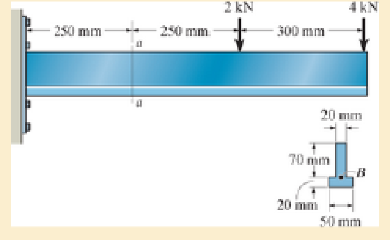
Probs. 7–24/25
Expert Solution & Answer
Want to see the full answer?
Check out a sample textbook solution
Students have asked these similar questions
6-105. The member has a square cross section and is
subjected to a resultant internal bending moment of
M = 850 N m as shown. Determine the stress at cach corner
and sketch the stress distribution produced by M. Set -30.
725 mm
125 mm
250 mm
M-850 N-m
Prob. 6-105
*6-104. The member has a square cross section and is
subjected to a resultant internal bending moment of
M = 850 N- m as shown. Determine the stress at cach corner
and sketch the stres distribution produced by M. Set 0=45°.
125 mm
125 mm
250 mm
M-850 N-m
D.
Prob. 6-104
8. If the allowable shear stress for each of the 10-mm-diameter steel pins at A, B, and C is
Ellow = 90 MPa, and the allowable normal stress for the 13-mm-diameter rod is Glow =
150 MPa, determine the largest intensity w of the uniform distributed load that can be
suspended from the beam.
1.2 m
B
0.9 g
Probs. 1-87/88
Chapter 7 Solutions
Mechanics of Materials
Ch. 7.2 - If the beam is subjected to a shear force of V =...Ch. 7.2 - Determine the shear stress at points A and B if...Ch. 7.2 - Determine the absolute maximum shear stress in the...Ch. 7.2 - If the beam is subjected to a shear force of V =20...Ch. 7.2 - If the beam is made from four plates and subjected...Ch. 7.2 - If the wide-flange beam is subjected to a shear of...Ch. 7.2 - If the wide-flange beam is subjected to a shear of...Ch. 7.2 - If the wide-flange beam is subjected to a shear of...Ch. 7.2 - The wood beam has an allowable shear stress of...Ch. 7.2 - The shaft is supported by a thrust bearing at A...
Ch. 7.2 - The shaft is supported by a thrust bearing at A...Ch. 7.2 - Determine the largest shear force V that the...Ch. 7.2 - If the applied shear force V = 18 kip, determine...Ch. 7.2 - The overhang beam is subjected to the uniform...Ch. 7.2 - The beam is made from a polymer and is subjected...Ch. 7.2 - Determine the maximum shear stress in the strut if...Ch. 7.2 - Determine the maximum shear force V that the strut...Ch. 7.2 - If the beam is subjected to a shear of V=15 kN,...Ch. 7.2 - If the wide-flange beam is subjected to a shear of...Ch. 7.2 - If the wide-flange beam is subjected to a shear of...Ch. 7.2 - Determine the length of the cantilevered beam so...Ch. 7.2 - If the beam is made from wood having an allowable...Ch. 7.2 - Determine the shear stress at point B on the web...Ch. 7.2 - Determine the maximum shear stress acting at...Ch. 7.2 - The beam is slit longitudinally along both sides....Ch. 7.2 - The beam is to be cut longitudinally along both...Ch. 7.2 - The beam has a rectangular cross section and is...Ch. 7.2 - The beam in Fig.6-48f is subjected to a fully...Ch. 7.3 - The two identical boards are bolted together to...Ch. 7.3 - Two identical 20-mm-thick plates are bolted to the...Ch. 7.3 - The boards are bolted together to form the...Ch. 7.3 - The boards are bolted together to form the...Ch. 7.3 - The beam is constructed from three boards. If it...Ch. 7.3 - The beam is constructed from three boards....Ch. 7.3 - Prob. 38PCh. 7.3 - A beam is constructed from three boards bolted...Ch. 7.3 - The T-beam is constructed as shown. If each nail...Ch. 7.3 - The member consists of two plastic channel strips...Ch. 7.3 - The beam is made from four boards nailed together...Ch. 7.3 - The beam is made from three polystyrene strips...Ch. 7.5 - A shear force of V=300 kN is applied to the box...Ch. 7.5 - A shear force of V=450 kN is applied to the box...Ch. 7.5 - A shear force of V = 18 kN is applied to the box...Ch. 7.5 - A shear force of V = 18 kN is applied to the box...Ch. 7.5 - The aluminum strut is 10 mm thick and has the...Ch. 7.5 - The aluminum strut is 10 mm thick and has the...Ch. 7.5 - The beam is subjected to a shear force of V=50...Ch. 7.5 - The beam is subjected to a shear force of V=50...Ch. 7.5 - The H-beam is subjected to a shear of V=80 kN...Ch. 7.5 - The H-beam is subjected to a shear of V=80 kN...Ch. 7.5 - The built-up beam is formed by welding together...Ch. 7.5 - The assembly is subjected to a vertical shear of V...Ch. 7 - The beam is fabricated from four boards nailed...Ch. 7 - The T-beam is subjected to a shear of V = 150 kN....Ch. 7 - The member is subject to a shear force of V = 2...Ch. 7 - Determine the shear stress at points B and C on...Ch. 7 - Determine the maximum shear stress acting at...
Additional Engineering Textbook Solutions
Find more solutions based on key concepts
What types of coolant are used in vehicles?
Automotive Technology: Principles, Diagnosis, and Service (5th Edition)
Define or describe each type of fluid: (a) viscoelastic fluid (b) pseudoplastic fluid (c) dilatant fluid (d) Bi...
Fluid Mechanics: Fundamentals and Applications
CONCEPT QUESTIONS
15.CQ3 The ball rolls without slipping on the fixed surface as shown. What is the direction ...
Vector Mechanics for Engineers: Statics and Dynamics
Select a mechanical component from Part 3 of this book (roller bearings, springs, etc.), go to the Internet, an...
Shigley's Mechanical Engineering Design (McGraw-Hill Series in Mechanical Engineering)
5.1 through 5.9
Locate the centroid of the plane area shown.
Fig. P5.1
Vector Mechanics for Engineers: Statics and Dynamics
Describe the structural changes that take place when a plain-carbon eutectoid steel is slowly cooled from the a...
Foundations of Materials Science and Engineering
Knowledge Booster


Learn more about
Need a deep-dive on the concept behind this application? Look no further. Learn more about this topic, mechanical-engineering and related others by exploring similar questions and additional content below.Similar questions
- F6-14. Determine the bending stress developed at corners A and B. What is the orientation of the neutral axis? 5 so N-m 100 mm 150 mm 100 mm 150 mm F6-14arrow_forward6-67. The rod is supported by smooth journal bearings at A and B that only exert vertical reactions on the shaft. If d = 90 mm, determine the absolute maximum bending stress in the beam, and sketch the stress distribution acting 12 kN/m over the cross section. B_ 3 m - 1.5 marrow_forward6-54. The beam is made from three boards nailed together as shown. If the moment acting on the cross section is M = 600 N - m, determine the maximum bending stress in the beam. Sketch a three-dimensional view of the stress distribution acting over the cross section. 25 mm 150 mm 20 mm 200 mm M - 600N-m 20 mmarrow_forward
- Determine the moment M that will produce a maximum stress of 70 MPa on the cross-section. 12 mm -75 mm- -12 mm 12 mm B 75 mm 250 mm -- 12 mmarrow_forward1.6-8 A frame is made of a 2 m long vertical pipe CD and a brace AB formed from two flat bars (see figure). The frame is supported by bolted connections at points A and C, which are 2 m apart. The brace is fastened to the pipe at point B,arrow_forwardThe shaft is supported by a smooth thrust bearing at A and a smooth journal bearing at B. Determine the resultant internal loadings acting on the cross-section at C.arrow_forward
- The pin is used to connect the three links together. Due to wear, the load is distributed over the top and bottom of the pin as shown on the free-body diagram. If the diameter of the pin is 0.40 in., determine the maximum bending stress on the cross-sectional area at the center section a–a. For the solution it is first necessary to determine the load intensities w1 and w2.arrow_forward7-25. Determine the maximum shear stress in the T-beam at section C. Show the result on a volume element at this point. 10 kN/m A |C 3 m -1.5 m--1.5 m-| 150 mm 150 mm |30 mm E - 30 mm Probs. 7-24/25arrow_forward*6-76. Determine the moment M that must be applied to the beam in order to create a maximum stress of 80 MPa. Also sketch the stress distribution acting over the cross section. 300 mm 20 mm M 260 mm 30 mm 30 mm 20 mm' 30 mmarrow_forward
- Determine the maximum bending stress in the handle of the cable cutter at section a–a. A force of 45 lb is applied to the handles.arrow_forwardThe shaft is supported by a journal bearing at A and a thrust bearing at B. Determine the normal force, shear force and moment at a section passing through (a) point C, which is just to right of bearing at A, and (b) point D, which is just to the left of the Force F2. Given: F1 = = 2.5 kip F2 = 3 kip lb W = 75 ft - b = 12 ft c = 2 ft a = 6 ft F2 D a barrow_forwardDetermine the shear stress at point B on the web of the cantilevered strut at section a–a.arrow_forward
arrow_back_ios
SEE MORE QUESTIONS
arrow_forward_ios
Recommended textbooks for you
 Elements Of ElectromagneticsMechanical EngineeringISBN:9780190698614Author:Sadiku, Matthew N. O.Publisher:Oxford University Press
 Mechanics of Materials (10th Edition)Mechanical EngineeringISBN:9780134319650Author:Russell C. HibbelerPublisher:PEARSON
 Thermodynamics: An Engineering ApproachMechanical EngineeringISBN:9781259822674Author:Yunus A. Cengel Dr., Michael A. BolesPublisher:McGraw-Hill Education
 Control Systems EngineeringMechanical EngineeringISBN:9781118170519Author:Norman S. NisePublisher:WILEY
 Mechanics of Materials (MindTap Course List)Mechanical EngineeringISBN:9781337093347Author:Barry J. Goodno, James M. GerePublisher:Cengage Learning
 Engineering Mechanics: StaticsMechanical EngineeringISBN:9781118807330Author:James L. Meriam, L. G. Kraige, J. N. BoltonPublisher:WILEY
Elements Of Electromagnetics
Mechanical Engineering
ISBN:9780190698614
Author:Sadiku, Matthew N. O.
Publisher:Oxford University Press
Mechanics of Materials (10th Edition)
Mechanical Engineering
ISBN:9780134319650
Author:Russell C. Hibbeler
Publisher:PEARSON
Thermodynamics: An Engineering Approach
Mechanical Engineering
ISBN:9781259822674
Author:Yunus A. Cengel Dr., Michael A. Boles
Publisher:McGraw-Hill Education
Control Systems Engineering
Mechanical Engineering
ISBN:9781118170519
Author:Norman S. Nise
Publisher:WILEY
Mechanics of Materials (MindTap Course List)
Mechanical Engineering
ISBN:9781337093347
Author:Barry J. Goodno, James M. Gere
Publisher:Cengage Learning
Engineering Mechanics: Statics
Mechanical Engineering
ISBN:9781118807330
Author:James L. Meriam, L. G. Kraige, J. N. Bolton
Publisher:WILEY
composite-materials; Author: Tonya Coffey;https://www.youtube.com/watch?v=Vu6ik-bcKf4;License: Standard youtube license