
Mechanics of Materials
11th Edition
ISBN: 9780137605460
Author: Russell C. Hibbeler
Publisher: Pearson Education (US)
expand_more
expand_more
format_list_bulleted
Videos
Textbook Question
thumb_up100%
Chapter 7.3, Problem 35P
The beam is constructed from three boards. Determine the maximum shear V that it can support if the allowable shear stress for the wood is τallow = 400 psi. What is the maximum allowable spacing s of the nails if each nail can resist a shear force of 400 lb?
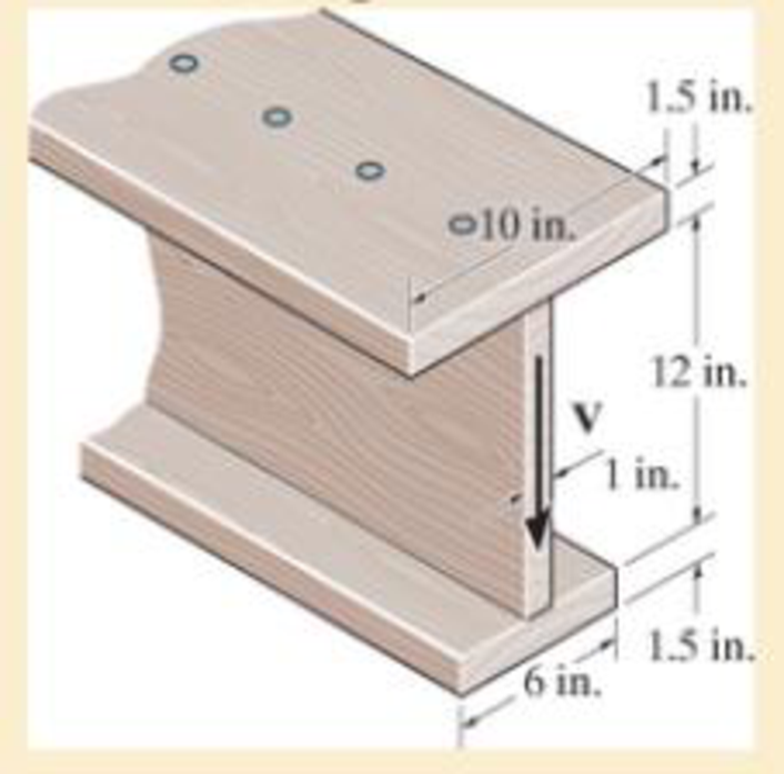
Probs. 7–34/35
Expert Solution & Answer
Want to see the full answer?
Check out a sample textbook solution
Students have asked these similar questions
The box beam is constructed from four boards that are fastened together using nails spaced along the beam every 2 in. If a force P = 2 kip is applied to the beam, determine the shear force resisted by each nail at A and B.
20 mm
20 mm
4. The simply supported beam on the right
is built up from three boards by nailing
them together as shown. If P = 12 kN,
determine the maximum allowable spacing
s of the nails to support the load, if each
nail can resist a shear force of 1.5 kN.
1 m
m
B
100 mm
25 mm-
25 mm
200 mm
25 mm
The double-web girder is constructed from two plywood sheets that are secured to wood members at its top and bottom. The allowable bending stress for the wood is σallow = 8 ksi and the allowable shear stress is τallow = 3 ksi. The fasteners are spaced s = 6 in. and each fastener can support 400 lb in single shear.
Determine the maximum load P that can be applied to the beam.
Chapter 7 Solutions
Mechanics of Materials
Ch. 7.2 - If the beam is subjected to a shear force of V =...Ch. 7.2 - Determine the shear stress at points A and B if...Ch. 7.2 - Determine the absolute maximum shear stress in the...Ch. 7.2 - If the beam is subjected to a shear force of V =20...Ch. 7.2 - If the beam is made from four plates and subjected...Ch. 7.2 - If the wide-flange beam is subjected to a shear of...Ch. 7.2 - If the wide-flange beam is subjected to a shear of...Ch. 7.2 - If the wide-flange beam is subjected to a shear of...Ch. 7.2 - The wood beam has an allowable shear stress of...Ch. 7.2 - The shaft is supported by a thrust bearing at A...
Ch. 7.2 - The shaft is supported by a thrust bearing at A...Ch. 7.2 - Determine the largest shear force V that the...Ch. 7.2 - If the applied shear force V = 18 kip, determine...Ch. 7.2 - The overhang beam is subjected to the uniform...Ch. 7.2 - The beam is made from a polymer and is subjected...Ch. 7.2 - Determine the maximum shear stress in the strut if...Ch. 7.2 - Determine the maximum shear force V that the strut...Ch. 7.2 - If the beam is subjected to a shear of V=15 kN,...Ch. 7.2 - If the wide-flange beam is subjected to a shear of...Ch. 7.2 - If the wide-flange beam is subjected to a shear of...Ch. 7.2 - Determine the length of the cantilevered beam so...Ch. 7.2 - If the beam is made from wood having an allowable...Ch. 7.2 - Determine the shear stress at point B on the web...Ch. 7.2 - Determine the maximum shear stress acting at...Ch. 7.2 - The beam is slit longitudinally along both sides....Ch. 7.2 - The beam is to be cut longitudinally along both...Ch. 7.2 - The beam has a rectangular cross section and is...Ch. 7.2 - The beam in Fig.6-48f is subjected to a fully...Ch. 7.3 - The two identical boards are bolted together to...Ch. 7.3 - Two identical 20-mm-thick plates are bolted to the...Ch. 7.3 - The boards are bolted together to form the...Ch. 7.3 - The boards are bolted together to form the...Ch. 7.3 - The beam is constructed from three boards. If it...Ch. 7.3 - The beam is constructed from three boards....Ch. 7.3 - Prob. 38PCh. 7.3 - A beam is constructed from three boards bolted...Ch. 7.3 - The T-beam is constructed as shown. If each nail...Ch. 7.3 - The member consists of two plastic channel strips...Ch. 7.3 - The beam is made from four boards nailed together...Ch. 7.3 - The beam is made from three polystyrene strips...Ch. 7.5 - A shear force of V=300 kN is applied to the box...Ch. 7.5 - A shear force of V=450 kN is applied to the box...Ch. 7.5 - A shear force of V = 18 kN is applied to the box...Ch. 7.5 - A shear force of V = 18 kN is applied to the box...Ch. 7.5 - The aluminum strut is 10 mm thick and has the...Ch. 7.5 - The aluminum strut is 10 mm thick and has the...Ch. 7.5 - The beam is subjected to a shear force of V=50...Ch. 7.5 - The beam is subjected to a shear force of V=50...Ch. 7.5 - The H-beam is subjected to a shear of V=80 kN...Ch. 7.5 - The H-beam is subjected to a shear of V=80 kN...Ch. 7.5 - The built-up beam is formed by welding together...Ch. 7.5 - The assembly is subjected to a vertical shear of V...Ch. 7 - The beam is fabricated from four boards nailed...Ch. 7 - The T-beam is subjected to a shear of V = 150 kN....Ch. 7 - The member is subject to a shear force of V = 2...Ch. 7 - Determine the shear stress at points B and C on...Ch. 7 - Determine the maximum shear stress acting at...
Knowledge Booster


Learn more about
Need a deep-dive on the concept behind this application? Look no further. Learn more about this topic, mechanical-engineering and related others by exploring similar questions and additional content below.Similar questions
- A wooden beam is fabricated by bolting together three members as shown. The 8-mm- diameter bolts are spaced at intervals of s= 200 mm along the x axis of the beam. If the internal shear force in the beam is V=7 kN, determine the shear stress in each bolt. 40 mm 40 mm 90 mm 40 mm 300 mmarrow_forwardThe boards are bolted together to form the built-up beam. If the beam is subjected to a shear force of V = 15 kip, determine the maximum spacing s of the bolts to the nearest 1 8 in. if each bolt has a shear strength of 6 kip.arrow_forwardDetermine the maximum shear stress acting in the fiberglass beam at the section where the internal shears force is maximum. (t1=15 mm, t2=20 mm, h=150 mm, b=50mm)arrow_forward
- Determine the maximum shear force V that the strut can support if the allowable shear stress for the material is tallow = 40 MPa.arrow_forwardTwo identical 20-mm-thick plates are bolted to the top and bottom flange to form the built-up beam. If the beam is subjected to a shear force of V = 300 kN, determine the maximum spacing s of the bolts to the nearest mm if eachbolt has a shear strength of 30 kN.arrow_forwardThe H-beam is subjected to a shear of V = 80 kN. Sketch the shear-stress distribution acting along with one of its side segments. Indicate all peak values.arrow_forward
- F12-7. Two identical 20-mm-thick plates are bolted to the top and bottom flange to form the built-up beam. If the beam is subjected to a shear force of V = 300 kN, determine the maximum spacing s of the bolts to the nearest mm if cach bolt has a shear strength of 30 kN. -200 mm 20 mm 10 mm 300 mm ho mm "20 mmarrow_forwardF7-9. The boards are bolted together to form the built-up beam. If the beam is subjected to a shear force of V = 15 kip, determine the allowable maximum spacing of the bolts to the nearest in. Each bolt has a shear strength of 6 kip. 1 in. 0.5 in. 0.5 in. 4 in. 3 in. 1 in, 1 in. 3 in. 4 in. F7-9arrow_forwardDetermine the stress distribution of the beam in cross section A-B when its dimensions are a = 4.0 m, b = 0.5 m, c = 124 mm, and d = 100 mm. The magnitude of the force P is 35 kN. How much are in cross section A-B normal force shear force bending moment normal stress at the top of the beam normal stress at the lower surface of the beam maximum shear stress shear stress at y = 62 mm from the lower levelarrow_forward
- The beam is subjected to a shear of V=39 kN V=39 kN. Set w=200 mm w=200 mm Part A Determine the web's shear stress at A. Part B Determine the web's shear stress at B.arrow_forward*7-12. The beam has a rectangular cross section and is made of wood having an allowable shear stress of Tallow = 200 psi. Determine the maximum shear force V that can be developed in the cross section of the beam. Also, plot the shear-stress variation over the cross section. 12 in. 8 in. Prob. 7-12arrow_forward4. If P = 20KN, determine the shear stress developed in pins at point A and C. The pins are subjected to double shear as shown, and each has a diameter of 18mm 30° ? 'B -2 m- + 2 m -2 m 5. The strut is glued to the horizontal member at surface AB. If the strut has thickness of 25mm and the glue can withstand an average shear stress of 600kPa, determine the maximum force P that can be applied strut. 50 mm. 60° Barrow_forward
arrow_back_ios
SEE MORE QUESTIONS
arrow_forward_ios
Recommended textbooks for you
 Elements Of ElectromagneticsMechanical EngineeringISBN:9780190698614Author:Sadiku, Matthew N. O.Publisher:Oxford University Press
 Mechanics of Materials (10th Edition)Mechanical EngineeringISBN:9780134319650Author:Russell C. HibbelerPublisher:PEARSON
 Thermodynamics: An Engineering ApproachMechanical EngineeringISBN:9781259822674Author:Yunus A. Cengel Dr., Michael A. BolesPublisher:McGraw-Hill Education
 Control Systems EngineeringMechanical EngineeringISBN:9781118170519Author:Norman S. NisePublisher:WILEY
 Mechanics of Materials (MindTap Course List)Mechanical EngineeringISBN:9781337093347Author:Barry J. Goodno, James M. GerePublisher:Cengage Learning
 Engineering Mechanics: StaticsMechanical EngineeringISBN:9781118807330Author:James L. Meriam, L. G. Kraige, J. N. BoltonPublisher:WILEY
Elements Of Electromagnetics
Mechanical Engineering
ISBN:9780190698614
Author:Sadiku, Matthew N. O.
Publisher:Oxford University Press
Mechanics of Materials (10th Edition)
Mechanical Engineering
ISBN:9780134319650
Author:Russell C. Hibbeler
Publisher:PEARSON
Thermodynamics: An Engineering Approach
Mechanical Engineering
ISBN:9781259822674
Author:Yunus A. Cengel Dr., Michael A. Boles
Publisher:McGraw-Hill Education
Control Systems Engineering
Mechanical Engineering
ISBN:9781118170519
Author:Norman S. Nise
Publisher:WILEY
Mechanics of Materials (MindTap Course List)
Mechanical Engineering
ISBN:9781337093347
Author:Barry J. Goodno, James M. Gere
Publisher:Cengage Learning
Engineering Mechanics: Statics
Mechanical Engineering
ISBN:9781118807330
Author:James L. Meriam, L. G. Kraige, J. N. Bolton
Publisher:WILEY
Mechanics of Materials Lecture: Beam Design; Author: UWMC Engineering;https://www.youtube.com/watch?v=-wVs5pvQPm4;License: Standard Youtube License