
Mechanics of Materials
11th Edition
ISBN: 9780137605460
Author: Russell C. Hibbeler
Publisher: Pearson Education (US)
expand_more
expand_more
format_list_bulleted
Videos
Textbook Question
Chapter 7.3, Problem 45P
The member consists of two plastic channel strips 0.5 in. thick, glued together at A and B. If the distributed load has a maximum intensity of W0=3 kip/ft, determine the maximum shear stress resisted by the glue.
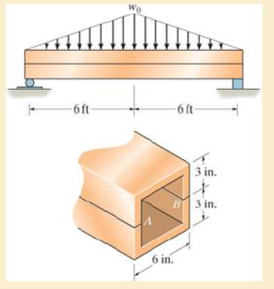
Prob. 7–45
Expert Solution & Answer
Want to see the full answer?
Check out a sample textbook solution
Students have asked these similar questions
The member consists of two plastic channel strips 0.5 in. thick, glued together at A and B. If the glue can support an allowable shear stress of tallow= 600 psi, determine the maximum intensity w0 of the triangular distributed loading that can be applied to the member based on the strength of the glue.
The rigid beam is supported at its ends by two A-36 steel tie rods. The rods have diameters dAB = 0.5 in. and dCD = 0.3 in. If the allowable stress for the steel is sallow = 16.2 ksi, determine the largest intensity of the distributed load w and its length x on the beam so that the beam remains in the horizontal position when it is loaded.
8. If the allowable shear stress for each of the 10-mm-diameter steel pins at A, B, and C is
Ellow = 90 MPa, and the allowable normal stress for the 13-mm-diameter rod is Glow =
150 MPa, determine the largest intensity w of the uniform distributed load that can be
suspended from the beam.
1.2 m
B
0.9 g
Probs. 1-87/88
Chapter 7 Solutions
Mechanics of Materials
Ch. 7.2 - If the beam is subjected to a shear force of V =...Ch. 7.2 - Determine the shear stress at points A and B if...Ch. 7.2 - Determine the absolute maximum shear stress in the...Ch. 7.2 - If the beam is subjected to a shear force of V =20...Ch. 7.2 - If the beam is made from four plates and subjected...Ch. 7.2 - If the wide-flange beam is subjected to a shear of...Ch. 7.2 - If the wide-flange beam is subjected to a shear of...Ch. 7.2 - If the wide-flange beam is subjected to a shear of...Ch. 7.2 - The wood beam has an allowable shear stress of...Ch. 7.2 - The shaft is supported by a thrust bearing at A...
Ch. 7.2 - The shaft is supported by a thrust bearing at A...Ch. 7.2 - Determine the largest shear force V that the...Ch. 7.2 - If the applied shear force V = 18 kip, determine...Ch. 7.2 - The overhang beam is subjected to the uniform...Ch. 7.2 - The beam is made from a polymer and is subjected...Ch. 7.2 - Determine the maximum shear stress in the strut if...Ch. 7.2 - Determine the maximum shear force V that the strut...Ch. 7.2 - If the beam is subjected to a shear of V=15 kN,...Ch. 7.2 - If the wide-flange beam is subjected to a shear of...Ch. 7.2 - If the wide-flange beam is subjected to a shear of...Ch. 7.2 - Determine the length of the cantilevered beam so...Ch. 7.2 - If the beam is made from wood having an allowable...Ch. 7.2 - Determine the shear stress at point B on the web...Ch. 7.2 - Determine the maximum shear stress acting at...Ch. 7.2 - The beam is slit longitudinally along both sides....Ch. 7.2 - The beam is to be cut longitudinally along both...Ch. 7.2 - The beam has a rectangular cross section and is...Ch. 7.2 - The beam in Fig.6-48f is subjected to a fully...Ch. 7.3 - The two identical boards are bolted together to...Ch. 7.3 - Two identical 20-mm-thick plates are bolted to the...Ch. 7.3 - The boards are bolted together to form the...Ch. 7.3 - The boards are bolted together to form the...Ch. 7.3 - The beam is constructed from three boards. If it...Ch. 7.3 - The beam is constructed from three boards....Ch. 7.3 - Prob. 38PCh. 7.3 - A beam is constructed from three boards bolted...Ch. 7.3 - The T-beam is constructed as shown. If each nail...Ch. 7.3 - The member consists of two plastic channel strips...Ch. 7.3 - The beam is made from four boards nailed together...Ch. 7.3 - The beam is made from three polystyrene strips...Ch. 7.5 - A shear force of V=300 kN is applied to the box...Ch. 7.5 - A shear force of V=450 kN is applied to the box...Ch. 7.5 - A shear force of V = 18 kN is applied to the box...Ch. 7.5 - A shear force of V = 18 kN is applied to the box...Ch. 7.5 - The aluminum strut is 10 mm thick and has the...Ch. 7.5 - The aluminum strut is 10 mm thick and has the...Ch. 7.5 - The beam is subjected to a shear force of V=50...Ch. 7.5 - The beam is subjected to a shear force of V=50...Ch. 7.5 - The H-beam is subjected to a shear of V=80 kN...Ch. 7.5 - The H-beam is subjected to a shear of V=80 kN...Ch. 7.5 - The built-up beam is formed by welding together...Ch. 7.5 - The assembly is subjected to a vertical shear of V...Ch. 7 - The beam is fabricated from four boards nailed...Ch. 7 - The T-beam is subjected to a shear of V = 150 kN....Ch. 7 - The member is subject to a shear force of V = 2...Ch. 7 - Determine the shear stress at points B and C on...Ch. 7 - Determine the maximum shear stress acting at...
Knowledge Booster


Learn more about
Need a deep-dive on the concept behind this application? Look no further. Learn more about this topic, mechanical-engineering and related others by exploring similar questions and additional content below.Similar questions
- The strut is glued to the horizontal member at surface AB. If the strut has a thickness of 25 mm and the glue can withstand an average shear stress of 600 kPa, determine the maximum force P that can be applied to the strut.arrow_forwardIf the load has a weight of 600 lb, determine the maximum normal stress on the cross section of the supporting member at section a–a. Also, plot the normalstress distribution over the cross section.arrow_forwardThe pin is used to connect the three links together. Due to wear, the load is distributed over the top and bottom of the pin as shown on the free-body diagram. If the diameter of the pin is 0.40 in., determine the maximum bending stress on the cross-sectional area at the center section a–a. For the solution it is first necessary to determine the load intensities w1 and w2.arrow_forward
- F7-7. Two klentical 20-mm thick plates are bollad to the top and bottom lange to form the buili-up heam. II the beam is subjected toa shear force of V = 300 KN, determine the allowable maximum spacing s of the boits to the nearest mm. Each bolt has a shcar strength of 30 RN. F7-9. The boards are boltod together to form the bull-up heam. Ir the beam is suhjactad to a shear force of V = 15 kip. determine the allowahle maximum spacing of the bolts le the nearst in. Each bolt has a shear strength of 6 kip. I in 05 in. 200 mm 3 in. 10 m 300 mm 10 mm 20 mm 7-9 FL7arrow_forward7-26. The beam is made from three boards glued together at the seams A and B. If it is subjected to the loading shown, determine the maximum vertical shear force resisted by the top flange of the beam. The supports at C and D exert only vertical reactions on the beam. 5 kip 5 kip 5 kip D - 4 ft 3 ft 1.5 ft 1.5 ft 4 ft 6 in. 1.5 in. 8 in. 2 in. B. 1.5 in. Tarrow_forward*1-60. The plug is used to close the end of the cylindrical tube that is subjected to an internal pressure of p = 650 Pa. Determine the average shear stress which the glue exerts on the sides of the tube needed to hold the cap in place. 35 mm P. 40 mm 25 mm' Prob. 1-60arrow_forward
- The simply supported beam is built up from three boards by nailing them together as A, В shown. Determine the L1 L2 maximum allowable bf spacing s of the nails to support that load, if each nail can resist a tf tw shear force of V kN. hw tf P=17KN V=2kN L1=3.1m L2=2.5m bf=120mm tf=20mm hw=270mm tw=15mmarrow_forwardThe 10-mm-diameter steel bolt is surrounded by a bronze sleeve. The outer diameter of this sleeve is 20 mm, and its inner diameter is 10 mm. If the bolt is subjected to a compressive force of P = 20 kN, determine the average normal stress in the steel and the bronze. Est = 200 GPa, Ebr = 100 GPa.arrow_forwardexplain how to find the resultant internal loading acting on the cross section at point A. Draw all necessary free-body diagrams, and indicate the relevant equations of equilibrium. Do not calculate values The lettered dimensions, angles, and loads are assumed to be known. P7-1. вarrow_forward
- F7-2 P7-3 Determine the absolute maximum shear stress developed in the beam. 3kip 61h. F-3arrow_forwardThe beam is constructed from three plastic strips. If the glue can support a shear stress of tallow = 8 kPa, determine the largest magnitude of the loads P that the beam can support.arrow_forwardThe steel pipe is filled with concrete and subjected to a compressive force of 80 kN. Determine the average normal stress in the concrete and the steel due to this loading. The pipe has an outer diameter of 80 mm and an inner diameter of 70 mm. E 200 GPa, Ec= 24 GPa.arrow_forward
arrow_back_ios
SEE MORE QUESTIONS
arrow_forward_ios
Recommended textbooks for you
 Elements Of ElectromagneticsMechanical EngineeringISBN:9780190698614Author:Sadiku, Matthew N. O.Publisher:Oxford University Press
 Mechanics of Materials (10th Edition)Mechanical EngineeringISBN:9780134319650Author:Russell C. HibbelerPublisher:PEARSON
 Thermodynamics: An Engineering ApproachMechanical EngineeringISBN:9781259822674Author:Yunus A. Cengel Dr., Michael A. BolesPublisher:McGraw-Hill Education
 Control Systems EngineeringMechanical EngineeringISBN:9781118170519Author:Norman S. NisePublisher:WILEY
 Mechanics of Materials (MindTap Course List)Mechanical EngineeringISBN:9781337093347Author:Barry J. Goodno, James M. GerePublisher:Cengage Learning
 Engineering Mechanics: StaticsMechanical EngineeringISBN:9781118807330Author:James L. Meriam, L. G. Kraige, J. N. BoltonPublisher:WILEY
Elements Of Electromagnetics
Mechanical Engineering
ISBN:9780190698614
Author:Sadiku, Matthew N. O.
Publisher:Oxford University Press
Mechanics of Materials (10th Edition)
Mechanical Engineering
ISBN:9780134319650
Author:Russell C. Hibbeler
Publisher:PEARSON
Thermodynamics: An Engineering Approach
Mechanical Engineering
ISBN:9781259822674
Author:Yunus A. Cengel Dr., Michael A. Boles
Publisher:McGraw-Hill Education
Control Systems Engineering
Mechanical Engineering
ISBN:9781118170519
Author:Norman S. Nise
Publisher:WILEY
Mechanics of Materials (MindTap Course List)
Mechanical Engineering
ISBN:9781337093347
Author:Barry J. Goodno, James M. Gere
Publisher:Cengage Learning
Engineering Mechanics: Statics
Mechanical Engineering
ISBN:9781118807330
Author:James L. Meriam, L. G. Kraige, J. N. Bolton
Publisher:WILEY
Differences between Temporary Joining and Permanent Joining.; Author: Academic Gain Tutorials;https://www.youtube.com/watch?v=PTr8QZhgXyg;License: Standard Youtube License