
Mechanics of Materials, 7th Edition
7th Edition
ISBN: 9780073398235
Author: Ferdinand P. Beer, E. Russell Johnston Jr., John T. DeWolf, David F. Mazurek
Publisher: McGraw-Hill Education
expand_more
expand_more
format_list_bulleted
Concept explainers
Videos
Textbook Question
Chapter 6.2, Problem 7P
A column is fabricated by connecting the rolled-steel members shown by bolts of
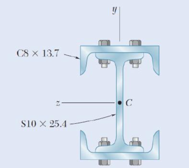
Fig. P6.7
Expert Solution & Answer

Trending nowThis is a popular solution!

Students have asked these similar questions
PROBLEM 8.40
A thin strap is wrapped around a solid rod of radius c= 20 mm as shown.
Knowing that I = 100 mm and F = 5 kN, determine the normal and
shearing stresses at (a) point H, (b) point K.
o = 79.6 MPa
T=7.96 MPa
O =0
T=13.26 MPa
1. The member BD is attached to a rod at B, to a hydraulic cylinder at C, and to a fixed
support at D. The bolt used at D acts in double shear and is made from a steel for
which the maximum allowable shearing stress is Tallow = 40 ksi. The rod AB is made
of a steel for which the maximum allowable tensile stress is Oallow = 60 ksi. The
upward hydraulic force applied at C is 12 kip.
1) Calculate the minimum diameter of the rod AB.
2) Calculate the minimum diameter of the bolt at D.
B
FAB
12 kip
8 in.
FBD
An elastomeric bearing (G=130 psi) is used to support a bridge girder as shown to provide flexibility during earthquakes. The beam must not displace more than 38 in. when a 5-kip lateral load is applied as shown. Knowing that the maximum allowable shearing stress is 60 psi, determine (a) the smallest allowable dimension b, (b) the smallest required thickness a.
Chapter 6 Solutions
Mechanics of Materials, 7th Edition
Ch. 6.2 - Three full-size 50 100-mm boards are nailed...Ch. 6.2 - For the built-up beam of Prob. 6.1, determine the...Ch. 6.2 - Three boards, each 2 in. thick, are nailed...Ch. 6.2 - A square box beam is made of two 20 80-mm planks...Ch. 6.2 - The American Standard rolled-steel beam shown has...Ch. 6.2 - The beam shown is fabricated by connecting two...Ch. 6.2 - A column is fabricated by connecting the...Ch. 6.2 - The composite beam shown is fabricated by...Ch. 6.2 - 6.9 through 6.12 For beam and loading shown,...Ch. 6.2 - 6.9 through 6.12 For beam and loading shown,...
Ch. 6.2 - 6.9 through 6.12 For beam and loading shown,...Ch. 6.2 - 6.9 through 6.12 For beam and loading shown,...Ch. 6.2 - 6.13 and 6.14 For a beam having the cross section...Ch. 6.2 - 6.13 and 6.14 For a beam having the cross section...Ch. 6.2 - For a timber beam having the cross section shown,...Ch. 6.2 - Two steel plates of 12 220-mm rectangular cross...Ch. 6.2 - Two W8 31 rolled sections may be welded at A and...Ch. 6.2 - For the beam and. loading shown, determine the...Ch. 6.2 - Fig. P6.19 6.19 A timber beam AB of length L and...Ch. 6.2 - A timber beam AB of Length L and rectangular cross...Ch. 6.2 - 6.21 and 6.22 For the beam and loading shown,...Ch. 6.2 - 6.21 and 6.22 For the beam and loading shown,...Ch. 6.2 - 6.23 and 6.24 For the beam and loading shown,...Ch. 6.2 - 6.23 and 6.24 For the beam and loading shown,...Ch. 6.2 - 6.25 through 6.28 A beam having the cross section...Ch. 6.2 - 6.25 through 6.28 A beam having the cross section...Ch. 6.2 - Prob. 27PCh. 6.2 - 6.25 through 6.28 A beam having the cross section...Ch. 6.5 - The built-up timber beam shown is subjected to a...Ch. 6.5 - The built-up beam shown is made by gluing together...Ch. 6.5 - The built-up beam was made by gluing together...Ch. 6.5 - Several wooden planks are glued together to form...Ch. 6.5 - The built-up wooden beam shown is subjected to a...Ch. 6.5 - Knowing that a W360 122 rolled-steel beam is...Ch. 6.5 - 6.35 and 6.36 An extruded aluminum beam has the...Ch. 6.5 - 6.35 and 6.36 An extruded aluminum beam has the...Ch. 6.5 - Knowing that a given vertical shear V causes a...Ch. 6.5 - The vertical shear is 1200 lb in a beam having the...Ch. 6.5 - The vertical shear is 1200 lb in a beam having the...Ch. 6.5 - 6.40 and 6.47 The extruded aluminum beam has a...Ch. 6.5 - Prob. 41PCh. 6.5 - Prob. 42PCh. 6.5 - Three planks are connected as shown by bolts of...Ch. 6.5 - A beam consists of three planks connected as shown...Ch. 6.5 - A beam consists of five planks of 1.5 6-in. cross...Ch. 6.5 - Four L102 102 9.5 steel angle shapes and a 12 ...Ch. 6.5 - A plate of 14-in. thickness is corrugated as shown...Ch. 6.5 - Prob. 48PCh. 6.5 - An extruded beam has the cross section shown and a...Ch. 6.5 - Prob. 50PCh. 6.5 - The design of a beam calls for connecting two...Ch. 6.5 - The cross section of an extruded beam is a hollow...Ch. 6.5 - Prob. 53PCh. 6.5 - Prob. 54PCh. 6.5 - Prob. 55PCh. 6.5 - 6.56 and 6.57 A composite beam is made by...Ch. 6.5 - 6.56 and 6.57 A composite beam is made by...Ch. 6.5 - Prob. 58PCh. 6.5 - Prob. 59PCh. 6.5 - Prob. 60PCh. 6.6 - 6.61 through 6.64 Determine the location of the...Ch. 6.6 - 6.61 through 6.64 Determine the location of the...Ch. 6.6 - 6.61 through 6.64 Determine the location of the...Ch. 6.6 - Prob. 64PCh. 6.6 - 6.65 through 6.68 An extruded beam has the cross...Ch. 6.6 - 6.65 through 6.68 An extruded beam has the cross...Ch. 6.6 - 6.65 through 6.68 An extruded beam has the cross...Ch. 6.6 - 6.65 through 6.68 An extruded beam has the cross...Ch. 6.6 - 6.69 through 6.74 Determine the location of the...Ch. 6.6 - Prob. 70PCh. 6.6 - Prob. 71PCh. 6.6 - Prob. 72PCh. 6.6 - Prob. 73PCh. 6.6 - Prob. 74PCh. 6.6 - Prob. 75PCh. 6.6 - 6.75 and 6.76 A thin-walled beam has the cross...Ch. 6.6 - 6.77 and 6.78 A thin-walled beam of uniform...Ch. 6.6 - Prob. 78PCh. 6.6 - Prob. 79PCh. 6.6 - Prob. 80PCh. 6.6 - Prob. 81PCh. 6.6 - Prob. 82PCh. 6.6 - Prob. 83PCh. 6.6 - Prob. 84PCh. 6.6 - Prob. 85PCh. 6.6 - Solve Prob. 6.85, assuming that the thickness of...Ch. 6.6 - Prob. 87PCh. 6.6 - Prob. 88PCh. 6 - Three boards are nailed together to form the beam...Ch. 6 - For the beam and loading shown, consider section...Ch. 6 - For the wide-flange beam with the loading shown,...Ch. 6 - For the beam and loading shown, consider section...Ch. 6 - The built-up timber beam is subjected to a 1500-lb...Ch. 6 - Knowing that a given vertical shear V causes a...Ch. 6 - Three planks are connected as shown by bolts of...Ch. 6 - Three 1 18-in. steel plates are bolted to four L6...Ch. 6 - The composite beam shown is made by welding C200 ...Ch. 6 - Prob. 98RPCh. 6 - A thin-walled beam of uniform thickness has the...Ch. 6 - Determine the location of the shear center O of a...
Knowledge Booster


Learn more about
Need a deep-dive on the concept behind this application? Look no further. Learn more about this topic, mechanical-engineering and related others by exploring similar questions and additional content below.Similar questions
- 5.86 The cast iron inverted T-section supports two concentrated loads of magni- tude P. The working stresses are 48 MPa in tension, 140 MPa in compression, and 30 MPa in shear. (a) Show that the neutral axis of the cross section is located at d = 48.75 mm and that the moment of inertia of the cross-sectional area about this axis is I = 11.918 x 106 mm“. (b) Find the maximum allowable value of P. 1.0 m 1.0 m 15 mm 3 m 150 mm NA- d 15 mm 150 mm FIG. P5.86arrow_forwardSECTION B(1) Question 1 The bell crank CBA is connected to a pin support B in double shear with 8-mm diameter pin B and to the 10-mm diameter rod CD. Knowing that the ultimate shearing stress is 110 MPa for the steel used in pin B and the ultimate normal stress is 230 MPa for the steel used in rod CD. Determine the maximum vertical force P that can be applied if an overall factor of safety of 1.5 is desired. 45% 300 mm B Figure 1 -450 mm-arrow_forward4. The solid cylinders AB and BC are bonded together at B and are attached to fixed supports at A and C. Knowing that the modulus of rigidity is 3.7 x 10⁶ psi for aluminum and 5.6 x 10⁶ psi for brass, determine the maximum shearing stress (a) in cylinder AB, (b) in cylinder BC. Aluminum- 12 in. <-1.5 in. B T = 12.5 kip-in. Brass -2.0 in. C 18 in.arrow_forward
- 1.4 kN - m PROBLEM 8.43 A 10-kN force and a 1.4-kN - m couple are applied at the top of the 65-mm diameter brass post shown. Determine the principal stresses and maximum shearing stress at (a) point H, (b) point K. 10 kN 240 mm Omax = 30.0 MPa O min =-30.0 MPa Tmax = 30.0 MPa Omax = 7.02 MPa Omin =-96.0 MPa Tmay =51.5 MPaarrow_forwardE' 3. For the 3-in.-diameter solid cylinder and loading shown, T = 40 kip-in., determine: (a) the polar moment of inertia, (b) the maximum shearing stress, (c) the maximum shearing strain, and (d) the angle of twist d. Use G=77 GPa for the modulus of rigidity and the length of the rod as 10 ft. 3 in.arrow_forwardTwo solid steel shafts (G = 77.2 GPa) are connected to a coupling disk B and to fixed supports at A and C. For the loading shown, determine (a) the reaction at each support, (b) the maximum shearing stress in shaft AB, (c) the maximum shearing stress in shaft BC. A 200 mm B 50 mm 250 mm 38 mm 1.4 kN. marrow_forward
- 8. The hydraulic cylinder CF, which partially controls the position of rod DE, has been locked in the position shown. Member BD is 5/8 in. thick and is connected to the vertical rod by a 3/8 in. – diameter bolt. Determine (a) the average shearing stress in the bolt, (b) the bearing stress at C in member BD. 7 in. D 75 20 E S in. 400 lb 1.S in.arrow_forwardPROBLEM 3.11 Knowing that each portion of the shaft AD consists of a solid circular rod, determine (a) the portion of the shaft in which the maximum shearing stress occurs, and (b) the magnitude of that stress. 56 N.m [Ans. (a) BC (b) 57.3 MPa] Tp = ? 135 N.m 45 N.m dcp - 24 mm dpc - 20 mm dAB = 16 mm Fig. P3.11 22:35 1404/2022 O BANG & OLU delete home end an ba 4 + backspace num lock Q W 9. po up %23 home caps lock D F Karrow_forwardTwo wooden planks, each 7/8 in thick and 6in wide, are joined by the glued mortise joint shown. Knowing that the wood used shears off along its grain when the average shearing stress reaches 120psi, determine the smallest allowable length d of the cuts if the joint is to withstand an axial load of magnitude P=1200-lb. Note: Seven surfaces carry the load, P=1200-lbarrow_forward
- TWO IDENTICAL LINKAGE-AND-HYDRAULIC-CYLINDER SYSTEMS CONTROL THE POSITION OF THE FORKS OF A FORK-LIFT TRUCK. THE LOAD SUPPORTED BY THEONE SYSTEM SHOWN IS 6750 N. KNOWING THAT THE THICKNESS OF MEMBER BD IS 16 MM, DETERMINE (A) THE AVERAGE SHEARING STRESS IN 13 MM DIAMETER PIN AT B, (B) THE BEARING STRESS AT B IN MEMBER BD. 300 mm 300 mm 6.750 N 375 mm 400 mm 400 mm 500 mmarrow_forward3.5 A torque T = 3 kN • m is applied to the solid bronze cylinder shown. Determine (a) the maximum shearing stress, (b) the shear- ing stress at point D, which lies on a 15-mm-radius circle drawn on the end of the cylinder, (e) the percent of the torque carried by the portion of the cylinder within the l15-mm radius. 60 mm 30 mm T=3 kN- m - 200 min Fig. P3.5arrow_forwardP.16.4 A thin-walled cantilever with walls of constant thickness t has the cross- section shown in Fig. P.16.4. It is loaded by a vertical force W at the tip and a horizontal force 2W at the mid-section, both forces acting through the shear centre. Determine and sketch the distribution of direct stress, according to the basic theory of bending, along the length of the beam for the points 1 and 2 of the cross-section. The wall thickness t can be taken as very small in comparison with d in calculating the sectional properties Lxx, Ixy, etc. Ans. 2,1 (mid-point) = -0.05 Wl/td², 02,1 (built-in end) = -1.85 Wl/td² ₂2 (mid-point) = -0.63 W1/td², 02 (built-in end) = 0.1 Wl/td². /////// Fig. P.16.4 W 7/2 2W 1/2 A 2 d12_ _d12. 3 Xarrow_forward
arrow_back_ios
SEE MORE QUESTIONS
arrow_forward_ios
Recommended textbooks for you
 Elements Of ElectromagneticsMechanical EngineeringISBN:9780190698614Author:Sadiku, Matthew N. O.Publisher:Oxford University Press
 Mechanics of Materials (10th Edition)Mechanical EngineeringISBN:9780134319650Author:Russell C. HibbelerPublisher:PEARSON
 Thermodynamics: An Engineering ApproachMechanical EngineeringISBN:9781259822674Author:Yunus A. Cengel Dr., Michael A. BolesPublisher:McGraw-Hill Education
 Control Systems EngineeringMechanical EngineeringISBN:9781118170519Author:Norman S. NisePublisher:WILEY
 Mechanics of Materials (MindTap Course List)Mechanical EngineeringISBN:9781337093347Author:Barry J. Goodno, James M. GerePublisher:Cengage Learning
 Engineering Mechanics: StaticsMechanical EngineeringISBN:9781118807330Author:James L. Meriam, L. G. Kraige, J. N. BoltonPublisher:WILEY
Elements Of Electromagnetics
Mechanical Engineering
ISBN:9780190698614
Author:Sadiku, Matthew N. O.
Publisher:Oxford University Press
Mechanics of Materials (10th Edition)
Mechanical Engineering
ISBN:9780134319650
Author:Russell C. Hibbeler
Publisher:PEARSON
Thermodynamics: An Engineering Approach
Mechanical Engineering
ISBN:9781259822674
Author:Yunus A. Cengel Dr., Michael A. Boles
Publisher:McGraw-Hill Education
Control Systems Engineering
Mechanical Engineering
ISBN:9781118170519
Author:Norman S. Nise
Publisher:WILEY
Mechanics of Materials (MindTap Course List)
Mechanical Engineering
ISBN:9781337093347
Author:Barry J. Goodno, James M. Gere
Publisher:Cengage Learning
Engineering Mechanics: Statics
Mechanical Engineering
ISBN:9781118807330
Author:James L. Meriam, L. G. Kraige, J. N. Bolton
Publisher:WILEY
Understanding Stress Transformation and Mohr's Circle; Author: The Efficient Engineer;https://www.youtube.com/watch?v=_DH3546mSCM;License: Standard youtube license