
Concept explainers
Videos
(a)
The points where the shearing stress is maximum and the values of the stress.
(a)
Answer to Problem 80P
The shearing stress is maximum at the points of
The maximum shear stress along the vertical leg is
The maximum shear stress along the horizontal leg is
The maximum shear stress at the corner of the leg is
Explanation of Solution
Calculation:
Refer to sample problem 6.6 in the text book.
Combined stress along the vertical leg
Combined stress along the horizontal leg
Modify Equation (1).
Calculate the point along the vertical leg differentiate both sides of the equation with respect to y as shown below.
Consider the condition
Hence, the shearing stress is maximum at the points of
Calculate the maximum shear stress along the vertical leg as shown below.
Substitute
Hence, the maximum shear stress along the vertical leg is
Modify Equation (2).
Calculate the point along the horizontal leg differentiate both sides of the equation with respect to z as shown below.
Consider the condition
Hence, the shearing stress is maximum at the points of
Calculate the maximum shear stress along the horizontal leg as shown below.
Substitute
Hence, the maximum shear stress along the horizontal leg is
The corner points of the horizontal and vertical legs are
Calculate the maximum shear stress at the corner point as shown below.
Substitute 0 for y in Equation (1).
Substitute 0 for z in Equation (2).
Therefore, the maximum shear stress at the corner of the leg is
(b)
Show that the points are located on the neutral axis for the loading P.
(b)
Answer to Problem 80P
The points y and z are located on the neutral axis for the loading P.
Explanation of Solution
Calculation:
Sketch the cross section along the neutral axis as shown below.
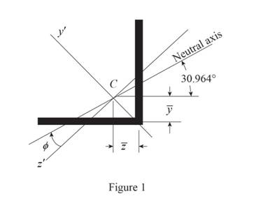
Refer to Figure 1.
Calculate the moment of inertia as shown below.
Along
Along
Consider the angle
Calculate angle
Substitute
Calculate the angle of the neutral axis from the horizontal as shown below.
Calculate the location of the centroid as shown below.
Along y axis:
Along z axis:
Calculate the neutral axis intersects for vertical leg as shown below.
Substitute
Calculate the neutral axis intersects for horizontal leg as shown below.
Substitute
Therefore, the points y and z are located on the neutral axis for the loading P
Want to see more full solutions like this?
Chapter 6 Solutions
Mechanics of Materials, 7th Edition


- I need the solution for this problem. Under normal operating conditions, the electric motor exerts a torque at point E of 12 kip-in. Knowing that each axis is solid, determine the maximum shear stress on (a) axis BC, (b) axis CD, (c) axis DE.arrow_forwardA 5/8-in.-diameter steel rod AB is fitted to a round hole near end C of the wooden member CD. For the loading shown, determine (a) the maximum average normal stress in the wood, (b) the distance b for which the average shearing stress is 100 psi on the surfaces indicated by the dashed lines, (c) the average bearing stress on the wood.arrow_forwardA steel pipe of 12-in. outer diameter is fabricated from 14-in.-thick plate by welding along a helix that forms an angle of 45° with a plane parallel to the axis of the pipe. Knowing that the maximum allowable tensile stress in the weld is 12 ksi, determine the largest torque that can be applied to the pipe.arrow_forward
- For the state of plane stress shown, use Mohr’s circle to determine (a) the largest value of τxy for which the maximum in-plane shearing stress is equal to or less than 12 ksi, (b) the corresponding principal stresses.arrow_forwardA centric load P is applied to the granite block shown. Knowing that the resulting maximum value of the shearing stress in the block is 2.5 ksi, determine (a) the magnitude of P, (b) the orientation of the surface on which the maximum shearing stress occurs, (c) the normal stress exerted on the surface, (d) the maximum value of the normal stress in the block.arrow_forwardThe hydraulic cylinder CF, which partially controls the position of rod DE, has been locked in the position shown. Member BD is 5/8 in.thick and is connected to the vertical rod by a 3/8-in.-diameter bolt.Determine (a) the average shearing stress in the bolt, (b) the bearing stress at C in member BD.arrow_forward
- a) For the 3-in.-diameter solid cylinder and loading shown, deter-mine the maximum shearing stress. (b) Determine the inner diameter of the 4-in.-diameter hollow cylinder shown, for which the maximum stress is the same as in part a.arrow_forwardTwo wooden planks, each 7/8 in thick and 6in wide, are joined by the glued mortise joint shown. Knowing that the wood used shears off along its grain when the average shearing stress reaches 120psi, determine the smallest allowable length d of the cuts if the joint is to withstand an axial load of magnitude P=1200-lb. Note: Seven surfaces carry the load, P=1200-lbarrow_forwardDetermine the diameter of the largest circular hole that can be punched into a sheet of polystyrene 6 mm thick, knowing that the force exerted by the punch is 45 kN and that a 55-MPa average shearing stress is required to cause the material to fail.arrow_forward
- Straight rods of 0.30-in. diameter and 200-ft length are sometimes used to clear underground conduits of obstructions or to thread wires through a new conduit. The rods are made of high-strength steel and, for storage and transportation, are wrapped on spools of 5-ft diameter. Assuming that the yield strength is not exceeded, determine (a) the maximum stress in a rod, when the rod, which was initially straight, is wrapped on the spool, (b) the corresponding bending moment in the rod. Use E= 29 * 106 psi.arrow_forwardKnowing that the couple shown acts in a vertical plane, determine the stress at (a) point A, (b) point B.arrow_forwardA torque of magnitude T=12 kN·m is applied to the end of a tank containing compressed air under a pressure of 8 MPa. Knowing that the tank has a 180-mm inner diameter and a 12-mm wall thickness, determine the maximum normal stress and the maximum in-plane shearing stress in the tank.arrow_forward
 Elements Of ElectromagneticsMechanical EngineeringISBN:9780190698614Author:Sadiku, Matthew N. O.Publisher:Oxford University Press
 Mechanics of Materials (10th Edition)Mechanical EngineeringISBN:9780134319650Author:Russell C. HibbelerPublisher:PEARSON
 Thermodynamics: An Engineering ApproachMechanical EngineeringISBN:9781259822674Author:Yunus A. Cengel Dr., Michael A. BolesPublisher:McGraw-Hill Education
 Control Systems EngineeringMechanical EngineeringISBN:9781118170519Author:Norman S. NisePublisher:WILEY
 Mechanics of Materials (MindTap Course List)Mechanical EngineeringISBN:9781337093347Author:Barry J. Goodno, James M. GerePublisher:Cengage Learning
 Engineering Mechanics: StaticsMechanical EngineeringISBN:9781118807330Author:James L. Meriam, L. G. Kraige, J. N. BoltonPublisher:WILEY