
Mechanics of Materials, 7th Edition
7th Edition
ISBN: 9780073398235
Author: Ferdinand P. Beer, E. Russell Johnston Jr., John T. DeWolf, David F. Mazurek
Publisher: McGraw-Hill Education
expand_more
expand_more
format_list_bulleted
Concept explainers
Videos
Textbook Question
Chapter 6.6, Problem 62P
6.61 through 6.64 Determine the location of the shear center O of a thin-walled beam of uniform thickness having the cross section shown.
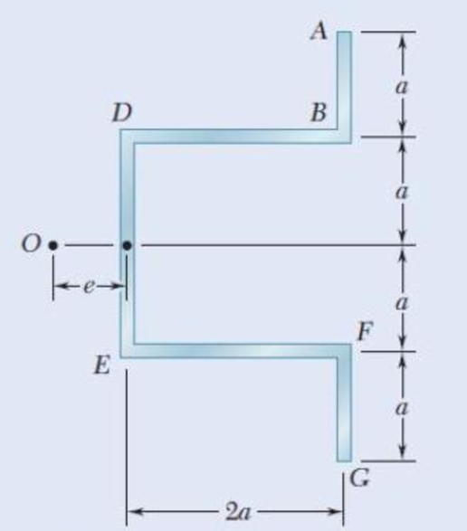
Fig, P6.62
Expert Solution & Answer
Want to see the full answer?
Check out a sample textbook solution
Students have asked these similar questions
The thin-walled Z-section beam as
shown in Fig.(1) when the shear load
S_y=100N, applied in the plane of
the web BC. The second moments of
area of the section about the x and y
axes are;
S₂
"
a. Ix = 41666.66 mm4
ly 10416.66mm 4
-
b. Ix=40066.67 mmª,
50mm
Iy = 30416.67mm4
c. Ix 11633.61 mm²,
Iy = 604110.61mm 4
d. None of the above
SA
Fig.(1)
B
G
SB
1mm
25mm
0.6 m
25 kN/m
40 kN
1.8 m
40 KN
C
0.6 m
D
PROBLEM 5.108
(a) Using singularity functions, write the equations for the shear and
bending moment for the beam and loading shown. (b) Determine the
maximum value of the bending moment in the beam.
4. A (250 mm) depth and (150mm) width rectangular beam is
subjected to maximum bending moment of (750 KN.m), Determine:
a. The maximum stress in the beam ?
b. If the value of Young Modulus (E) for the beam material is (200
GPa), find the radius of curvature for that portion of the beam where
the bending is maximum ?
c. The value of the longitudinal stress at a distance of (65mm) from
the top surface of the beam ?
Chapter 6 Solutions
Mechanics of Materials, 7th Edition
Ch. 6.2 - Three full-size 50 100-mm boards are nailed...Ch. 6.2 - For the built-up beam of Prob. 6.1, determine the...Ch. 6.2 - Three boards, each 2 in. thick, are nailed...Ch. 6.2 - A square box beam is made of two 20 80-mm planks...Ch. 6.2 - The American Standard rolled-steel beam shown has...Ch. 6.2 - The beam shown is fabricated by connecting two...Ch. 6.2 - A column is fabricated by connecting the...Ch. 6.2 - The composite beam shown is fabricated by...Ch. 6.2 - 6.9 through 6.12 For beam and loading shown,...Ch. 6.2 - 6.9 through 6.12 For beam and loading shown,...
Ch. 6.2 - 6.9 through 6.12 For beam and loading shown,...Ch. 6.2 - 6.9 through 6.12 For beam and loading shown,...Ch. 6.2 - 6.13 and 6.14 For a beam having the cross section...Ch. 6.2 - 6.13 and 6.14 For a beam having the cross section...Ch. 6.2 - For a timber beam having the cross section shown,...Ch. 6.2 - Two steel plates of 12 220-mm rectangular cross...Ch. 6.2 - Two W8 31 rolled sections may be welded at A and...Ch. 6.2 - For the beam and. loading shown, determine the...Ch. 6.2 - Fig. P6.19 6.19 A timber beam AB of length L and...Ch. 6.2 - A timber beam AB of Length L and rectangular cross...Ch. 6.2 - 6.21 and 6.22 For the beam and loading shown,...Ch. 6.2 - 6.21 and 6.22 For the beam and loading shown,...Ch. 6.2 - 6.23 and 6.24 For the beam and loading shown,...Ch. 6.2 - 6.23 and 6.24 For the beam and loading shown,...Ch. 6.2 - 6.25 through 6.28 A beam having the cross section...Ch. 6.2 - 6.25 through 6.28 A beam having the cross section...Ch. 6.2 - Prob. 27PCh. 6.2 - 6.25 through 6.28 A beam having the cross section...Ch. 6.5 - The built-up timber beam shown is subjected to a...Ch. 6.5 - The built-up beam shown is made by gluing together...Ch. 6.5 - The built-up beam was made by gluing together...Ch. 6.5 - Several wooden planks are glued together to form...Ch. 6.5 - The built-up wooden beam shown is subjected to a...Ch. 6.5 - Knowing that a W360 122 rolled-steel beam is...Ch. 6.5 - 6.35 and 6.36 An extruded aluminum beam has the...Ch. 6.5 - 6.35 and 6.36 An extruded aluminum beam has the...Ch. 6.5 - Knowing that a given vertical shear V causes a...Ch. 6.5 - The vertical shear is 1200 lb in a beam having the...Ch. 6.5 - The vertical shear is 1200 lb in a beam having the...Ch. 6.5 - 6.40 and 6.47 The extruded aluminum beam has a...Ch. 6.5 - Prob. 41PCh. 6.5 - Prob. 42PCh. 6.5 - Three planks are connected as shown by bolts of...Ch. 6.5 - A beam consists of three planks connected as shown...Ch. 6.5 - A beam consists of five planks of 1.5 6-in. cross...Ch. 6.5 - Four L102 102 9.5 steel angle shapes and a 12 ...Ch. 6.5 - A plate of 14-in. thickness is corrugated as shown...Ch. 6.5 - Prob. 48PCh. 6.5 - An extruded beam has the cross section shown and a...Ch. 6.5 - Prob. 50PCh. 6.5 - The design of a beam calls for connecting two...Ch. 6.5 - The cross section of an extruded beam is a hollow...Ch. 6.5 - Prob. 53PCh. 6.5 - Prob. 54PCh. 6.5 - Prob. 55PCh. 6.5 - 6.56 and 6.57 A composite beam is made by...Ch. 6.5 - 6.56 and 6.57 A composite beam is made by...Ch. 6.5 - Prob. 58PCh. 6.5 - Prob. 59PCh. 6.5 - Prob. 60PCh. 6.6 - 6.61 through 6.64 Determine the location of the...Ch. 6.6 - 6.61 through 6.64 Determine the location of the...Ch. 6.6 - 6.61 through 6.64 Determine the location of the...Ch. 6.6 - Prob. 64PCh. 6.6 - 6.65 through 6.68 An extruded beam has the cross...Ch. 6.6 - 6.65 through 6.68 An extruded beam has the cross...Ch. 6.6 - 6.65 through 6.68 An extruded beam has the cross...Ch. 6.6 - 6.65 through 6.68 An extruded beam has the cross...Ch. 6.6 - 6.69 through 6.74 Determine the location of the...Ch. 6.6 - Prob. 70PCh. 6.6 - Prob. 71PCh. 6.6 - Prob. 72PCh. 6.6 - Prob. 73PCh. 6.6 - Prob. 74PCh. 6.6 - Prob. 75PCh. 6.6 - 6.75 and 6.76 A thin-walled beam has the cross...Ch. 6.6 - 6.77 and 6.78 A thin-walled beam of uniform...Ch. 6.6 - Prob. 78PCh. 6.6 - Prob. 79PCh. 6.6 - Prob. 80PCh. 6.6 - Prob. 81PCh. 6.6 - Prob. 82PCh. 6.6 - Prob. 83PCh. 6.6 - Prob. 84PCh. 6.6 - Prob. 85PCh. 6.6 - Solve Prob. 6.85, assuming that the thickness of...Ch. 6.6 - Prob. 87PCh. 6.6 - Prob. 88PCh. 6 - Three boards are nailed together to form the beam...Ch. 6 - For the beam and loading shown, consider section...Ch. 6 - For the wide-flange beam with the loading shown,...Ch. 6 - For the beam and loading shown, consider section...Ch. 6 - The built-up timber beam is subjected to a 1500-lb...Ch. 6 - Knowing that a given vertical shear V causes a...Ch. 6 - Three planks are connected as shown by bolts of...Ch. 6 - Three 1 18-in. steel plates are bolted to four L6...Ch. 6 - The composite beam shown is made by welding C200 ...Ch. 6 - Prob. 98RPCh. 6 - A thin-walled beam of uniform thickness has the...Ch. 6 - Determine the location of the shear center O of a...
Knowledge Booster


Learn more about
Need a deep-dive on the concept behind this application? Look no further. Learn more about this topic, mechanical-engineering and related others by exploring similar questions and additional content below.Similar questions
- A 3.6 m long overhang timber beam AC with a 2.4 m span AB is to be designed to support the distributed and concentrated loads shown. a. Determine the maximum moment of the beam. b. Determine the minimum required depth of the beam if the allowable stress is 12 MPa. c. Determine the maximum shearing stress of the required beam. 20 kN 90 mm 60 kN/m 2.4 m 1.2 marrow_forward5.7 For the cantilever beam shown in the figure, find (a) the maximum bending stress and its location; and (b) the bending stress at a point 20 mm from the top of the beam on section B. 1.0 kN/m 150 mm C A 2 m- 50 mm 6 m FIG. PS.7arrow_forwardProblem 6.1 A cantilever beam is subject to an end force of 15 kN inclined at 15° to the horizontal axis of the beam. The beam is 150 mm long with a rectangular section 50 mm wide x 25 mm deep. Determine the net stress distribution across the fixed end section.arrow_forward
- 5.16 The box beam is made by nailing four 2-in. by 8-in. planks together as shown. (a) Show that the moment of inertia of the cross-sectional area about the neutral axis is 981.3 in.. (b) Given that wo 300 lb/ft, find the largest allowable force P if the bending stress is limited to 1400 psi. 8 in.2 in. 8 in. 9 f 3 ft 2 in. FIG. P5.16arrow_forward(14) A beam of I-section is 2 in. wide and 4 in. deep with all sections 1/2 in. thick. It is supported at points 5ft. apart, and carries a concentrated load of 400 lb at a distance of 2ft from the left support. (a) Determine the horizontal shear in the vertical section just to the left of the load and at distances of 0, 1, and 2 in. from the neutral axis. (b) Determine the horizontal shear in the vertical section just to the right of the left support and at distances 0, 1, and 1 ½ in. from the neutral axis.arrow_forwardProb. #2. An overhanging beam with a length of 12 ft. is fixed at the left end. It has a load of uniformly distributed load of 100 lb/ft located 4 ft fr. The left support and covers the remaining length of the beam. Draw completely the shear and bending moment for this beam.arrow_forward
- I need help solving Problem 5.16. For the beam and loading shown, determine the maximum normal stress due to bending on a transverse section at C.arrow_forwardQ4. An extruded beam has the cross-section shown. Determine (a) the location of the shear centre O, and (b) the distribution of shear stress caused by a 110 kN vertical shear force applied at O. [Ans. e 19.8 mm, member BD: T = 24.23 MPa at B; T = 56.54 MPa at C] 12mm O e B V = 110 kN 6mm ↓ C A 6mm 200mmarrow_forward201 (A) Q: For the beam ABCD carries a uniformly distributed load (w) as shown in the figure below. Portions AB and CD of the beam is hollow. If the allowable bending stress is 60 MPa, determine (1) the largest allowable value of the uniformly distributed load (w) that can be applied to the beam; (2) the bending stresse at a point that is 30 mm above the bottom of the beam at the section of maximum positive moment. 20mm w kN/m 200mm 160mm 2m 2m 20mm A AT 2 m B 20mm H 60mm 20mm Sec. (AB), (CD) 100mm Sec. (BC)arrow_forward
- Determine the largest permissible value of P for the beam and loading shown, knowing that the allowable normal stress is +4 ksi in tension and -9 ksi in compression. Solve for P (Note: Draw the shear and moment diagram). |P |P 1 in. -10 in. 10 in- A E 5 in. B |C D 1 in. 7 in. 60 in. 60 in.arrow_forwardA simply supported wood beam that is 6.6 m long carries a 49 kN concentrated load at B. The cross-sectional dimensions of the beam are b = 120 mm, d = 450 mm, a = 105 mm, and c = 50 mm. Section a-a is located at x = 1.1 m from B. (a) At section a-a, determine the magnitude of the shear stress in the beam at point H. (b) At section a-a, determine the magnitude of the shear stress in the beam at point K. (c) Determine the maximum horizontal shear stress that occurs in the beam at any location within the entire span. (d) Determine the maximum tensile bending stress that occurs in the beam at any location within the entire length. H a A B C 2L b 3 Answer: (a) TH = i kPa (b) TK = i kPa (c) Tmax i kPa (d) Omax= i MPaarrow_forwardProblems A plate 10 mm thick is subjected to bending moments My equal to 10 Nm/mm and My equal to 5 Nm/mm. Calculate the maximum direct stresses in the plate. P.7.1arrow_forward
arrow_back_ios
SEE MORE QUESTIONS
arrow_forward_ios
Recommended textbooks for you
 Elements Of ElectromagneticsMechanical EngineeringISBN:9780190698614Author:Sadiku, Matthew N. O.Publisher:Oxford University Press
 Mechanics of Materials (10th Edition)Mechanical EngineeringISBN:9780134319650Author:Russell C. HibbelerPublisher:PEARSON
 Thermodynamics: An Engineering ApproachMechanical EngineeringISBN:9781259822674Author:Yunus A. Cengel Dr., Michael A. BolesPublisher:McGraw-Hill Education
 Control Systems EngineeringMechanical EngineeringISBN:9781118170519Author:Norman S. NisePublisher:WILEY
 Mechanics of Materials (MindTap Course List)Mechanical EngineeringISBN:9781337093347Author:Barry J. Goodno, James M. GerePublisher:Cengage Learning
 Engineering Mechanics: StaticsMechanical EngineeringISBN:9781118807330Author:James L. Meriam, L. G. Kraige, J. N. BoltonPublisher:WILEY
Elements Of Electromagnetics
Mechanical Engineering
ISBN:9780190698614
Author:Sadiku, Matthew N. O.
Publisher:Oxford University Press
Mechanics of Materials (10th Edition)
Mechanical Engineering
ISBN:9780134319650
Author:Russell C. Hibbeler
Publisher:PEARSON
Thermodynamics: An Engineering Approach
Mechanical Engineering
ISBN:9781259822674
Author:Yunus A. Cengel Dr., Michael A. Boles
Publisher:McGraw-Hill Education
Control Systems Engineering
Mechanical Engineering
ISBN:9781118170519
Author:Norman S. Nise
Publisher:WILEY
Mechanics of Materials (MindTap Course List)
Mechanical Engineering
ISBN:9781337093347
Author:Barry J. Goodno, James M. Gere
Publisher:Cengage Learning
Engineering Mechanics: Statics
Mechanical Engineering
ISBN:9781118807330
Author:James L. Meriam, L. G. Kraige, J. N. Bolton
Publisher:WILEY
Everything About COMBINED LOADING in 10 Minutes! Mechanics of Materials; Author: Less Boring Lectures;https://www.youtube.com/watch?v=N-PlI900hSg;License: Standard youtube license