
Concept explainers
Videos
(a)
Show that the magnitude of the horizontal shearing force H exerted on the lower face of the portion of the beam ACKJ is
(a)
Answer to Problem 60P
The magnitude of the horizontal shearing force H exerted on the lower face of the portion of the beam ACKJ is
Explanation of Solution
Given information:
K is a point at a distance
Calculation:
The point K is located a distance y above the neutral axis.
Provide the stress distribution as shown below.
Sketch the stress distribution for
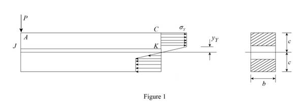
Sketch the stress distribution for
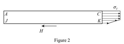
Calculate the horizontal forces acting on ACKJ as shown below.
Substitute
Therefore, the magnitude of the horizontal shearing force H exerted on the lower face of the portion of the beam ACKJ is
(b)
The shearing stress at K.
(b)
Answer to Problem 60P
The shearing stress at K is
Explanation of Solution
Given information:
K is a point at a distance
Calculation:
Refer to part (a).
The horizontal shearing force is
Calculate the shear stress as shown below.
Substitute
Provide the relation of moment as shown below.
Differentiate both sides of the Equation as shown below.
Substitute
Substitute
Therefore, the shearing stress at K is
Want to see more full solutions like this?
Chapter 6 Solutions
Mechanics of Materials, 7th Edition


- 4. A (250 mm) depth and (150mm) width rectangular beam is subjected to maximum bending moment of (750 KN.m), Determine: a. The maximum stress in the beam ? b. If the value of Young Modulus (E) for the beam material is (200 GPa), find the radius of curvature for that portion of the beam where the bending is maximum ? c. The value of the longitudinal stress at a distance of (65mm) from the top surface of the beam ?arrow_forward5.16 The box beam is made by nailing four 2-in. by 8-in. planks together as shown. (a) Show that the moment of inertia of the cross-sectional area about the neutral axis is 981.3 in.. (b) Given that wo 300 lb/ft, find the largest allowable force P if the bending stress is limited to 1400 psi. 8 in.2 in. 8 in. 9 f 3 ft 2 in. FIG. P5.16arrow_forward(B) Q: The cantilever beam shown below has a circular cross section of 50mm outer diameter. Portion AB of the beam is hollow, with an inner diameter of 35mm. If the allowable bending stress is 140 MPa, determine (1) the largest allowable uniformly distributed load (w) that can be applied to the beam; (2) the bending stress at a point that is 7 mm below the top of the beam at section D. 50 mm W D B O! 35 mm A - 750 mm 250 mmarrow_forward
- PROBLEM 5.21 For the beam and loading shown, determine the maximum bending stress on a transverse section at C. [Ans. 10.89 MPa] 10 kN 3 kN/m 100 mm 25 de 200 mm B 1.5 m 1.5 m X-X 2.2 m splay E23 Fig. P5.21 Chp Show all 205 14 04/22 ALING • SPARKLING PURDEY'S NATURAL ENERGT REFOCUS Dark Fruits with guarana Paune hp Prien Sem Sysha Scroll Serril Lock F11 F10 F9 Num Lock F8 Page Up F7 F6 Home F5 bert F4 7 Page Down Home End Deletearrow_forwardQ4. An extruded beam has the cross-section shown. Determine (a) the location of the shear centre O, and (b) the distribution of shear stress caused by a 110 kN vertical shear force applied at O. [Ans. e 19.8 mm, member BD: T = 24.23 MPa at B; T = 56.54 MPa at C] 12mm O e B V = 110 kN 6mm ↓ C A 6mm 200mmarrow_forward6.2 Derive the expression for the maximum deflection of a simply supported beam of negligible weight carrying a point load at its mid-span position. The distance between the supports is L, the second moment of area of the cross-section is I and the modulus of elasticity of the beam material is E. The maximum deflection of such a simply supported beam of length 3 m is 4.3 mm when carrying a load of 200 kN at its mid-span position. What would be the deflection at the free end of a cantilever of the same material, length and cross-section if it carries a load of 100 kN at a point 1.3 m from the free end? [13.4 mm]arrow_forward
- 0.6 m 25 kN/m 40 kN 1.8 m 40 KN C 0.6 m D PROBLEM 5.108 (a) Using singularity functions, write the equations for the shear and bending moment for the beam and loading shown. (b) Determine the maximum value of the bending moment in the beam.arrow_forwardThe thin-walled Z-section beam as shown in Fig.(1) when the shear load S_y=100N, applied in the plane of the web BC. The second moments of area of the section about the x and y axes are; S₂ " a. Ix = 41666.66 mm4 ly 10416.66mm 4 - b. Ix=40066.67 mmª, 50mm Iy = 30416.67mm4 c. Ix 11633.61 mm², Iy = 604110.61mm 4 d. None of the above SA Fig.(1) B G SB 1mm 25mmarrow_forwardA beam is carrying a moment M as indicated. The cross section of the beam is symmetric about the z axis. The dimensions of the cross section and the location of the centroid (point C) are shown. Knowing that Iy = 280,000 mm4, Iz = 150,000 mm4, and M = 400,000 + UV in N.mm, where UV is 21(a) Calculate the components of the bending moment on the y and z axes, Myand Mz.(b) Identify which point at the cross section has the largest tensile stress, and which point at the cross section has the largest compressive stress.(c) Calculate the maximum tensile stress and the maximum compressive stress in the cross sectionarrow_forward
- PROBLEM 4.The beam AB consisting of a cast iron plate of uniform thickness, b, and length, L, is to support the distributed load w(x) shown a) Knowing that the beam is to be of constant strength (fully stressed beam), express h in terms of x, L and ho. b) Determine the smallest value of ho if L=800 mm, b=25 mm, wo=300 kN/m and oall=200 MPa. w-=WoCos(ITX/2L) A ho Barrow_forwardA beam with a distributed load w = 1 kN/m and a point application of a moment M 1 kN-m (at point B) is shown below. The length of the beam from point A to point D is 10 m, while the distance from A to B is 4 m, the distance from B to C is 4 m, and the distance from C to D is 2 m. Determine the locations along the length of the beam (distances from A) where the internal moment is zero.arrow_forwardTwo beams A and B are simply supported, subjected to identical loads. The two beams have same width, but depth of beam A is double the depth of beam B. The ratio of their section modulus is (a) 2 (b) 3 (c) 4 (d) 8arrow_forward
 Elements Of ElectromagneticsMechanical EngineeringISBN:9780190698614Author:Sadiku, Matthew N. O.Publisher:Oxford University Press
 Mechanics of Materials (10th Edition)Mechanical EngineeringISBN:9780134319650Author:Russell C. HibbelerPublisher:PEARSON
 Thermodynamics: An Engineering ApproachMechanical EngineeringISBN:9781259822674Author:Yunus A. Cengel Dr., Michael A. BolesPublisher:McGraw-Hill Education
 Control Systems EngineeringMechanical EngineeringISBN:9781118170519Author:Norman S. NisePublisher:WILEY
 Mechanics of Materials (MindTap Course List)Mechanical EngineeringISBN:9781337093347Author:Barry J. Goodno, James M. GerePublisher:Cengage Learning
 Engineering Mechanics: StaticsMechanical EngineeringISBN:9781118807330Author:James L. Meriam, L. G. Kraige, J. N. BoltonPublisher:WILEY