
Videos
Three boards are nailed together to form the beam shown, which is subjected to a vertical shear. Knowing that the spacing between the nails is s = 75 mm and that the allowable shearing force in each nail is 400 N, determine the allowable shear when w = 120 mm.
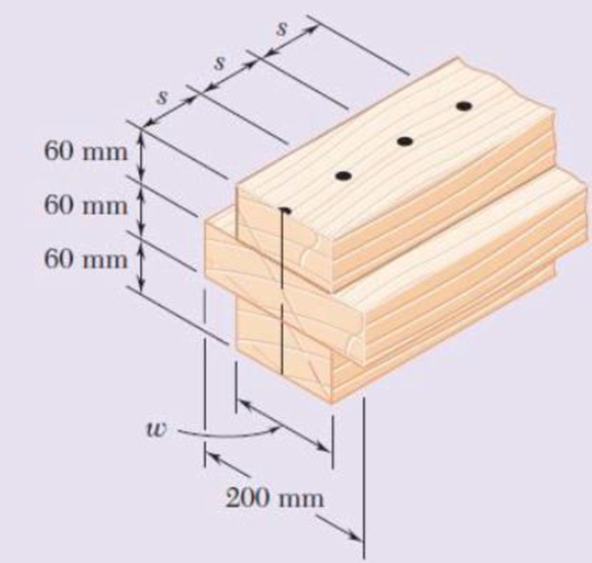
Fig. p6.89
The allowable shear in the beam.
Answer to Problem 89RP
The allowable shear in the beam is
Explanation of Solution
Given information:
The spacing between the nails is
The allowable shearing in each nail is
Calculation:
Sketch the cross section as shown in Figure 1.
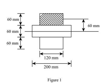
Refer to Figure 1.
Calculate the moment of inertia (I) as shown below.
Here, b is the breadth of the section, h is the height of the section, A is the area of the beam, and
Calculate the moment of inertia for the whole symmetrical section as shown below.
Calculate the first moment of area (Q) as shown below.
Calculate the horizontal shear per unit length (q) as shown below.
Here, V is the vertical shear.
Substitute
Calculate the allowable shear
Substitute
Therefore, the allowable shear is
Want to see more full solutions like this?
Chapter 6 Solutions
Mechanics of Materials, 7th Edition


- Three 1 x 18-in. steel plates are bolted to four L6 x 6 x 1 angles to form a beam with the cross section shown. The bolts have a 78-in. diameter and are spaced longitudinally every 5 in. Knowing that the allowable average shearing stress in the bolts is 12 ksi, determine the largest permissible vertical shear in the beam. (Given: Ix= 6123 in4.)arrow_forwardA square box beam is made of two 20 x 80-mm planks and two 20 x 120-mm planks nailed together as shown. Knowing that the spacing between the nails is s= 30 mm and that the vertical shear in the beam is V=1200 N, determine (a) the shearing force in each nail, (b) the maximum shearing stress in the beam.arrow_forwardThe American Standard rolled-steel beam shown has been reinforced by attaching to it two 16 x 200-mm plates, using 18-mm-diameter bolts spaced longitudinally every 120 mm. Knowing that the average allowable shearing stress in the bolts is 90 MPa, determine the largest permissible vertical shearing force.arrow_forward
- two 20 x 100-mm and two 20 x 180 mm boards are glued together as shown to form a 120 x 200 mm box beam. Knowing that the beams are subjected to a vertical shear of 3.625 kN. Determin the average shearing stress in the glued joint at Barrow_forwardKnowing that a given vertical shear V causes a maximum shearing stress of 50 MPa in a thin-walled member having the cross section shown, determine the corresponding shearing stress at (a) point a, (b) point b, (c) point c.arrow_forwardFor the wide-flange beam with the loading shown, determine the largest load P that can be applied, knowing that the maximum normal stress is 160 MPa and the largest shearing stress is 100 MPa. W360 x 122 Barrow_forward
- An extruded aluminum beam has the cross section shown. Knowing that the vertical shear in the beam is 150 kN, determine the corresponding shearing stress at (a) point a, (b) point b.arrow_forwardThree boards are nailed together to form a beam shown, which is sub-jected to a vertical shear. Knowing that the spacing between the nails is s5 75 mm and that the allowable shearing force in each nail is 400 N, determine the allowable shear when w= 100 mmarrow_forwardA square box beam is made of two 3434 × 3.5-in. planks and two 3434 × 5-in. planks nailed together as shown. Know that the spacing between the nails is s = 1.25 in. and that the vertical shear in the beam is V = 260 lb. Determine the maximum shearing stress in the beam.arrow_forward
- A composite beam is made by attaching the timber and steel portions shown with bolts of 12-mm diameter spaced longitudinally every 200 mm. The modulus of elasticity is 10 GPa for the wood and 200 GPa for the steel. For a vertical shear of 4 kN, determine (a) the average shearing stress in the bolts, (b) the shearing stress at the center of the cross section.arrow_forwardLink AB, of width b = 50 mm and thickness t = 6 mm, is used to support the end of a horizontal beam. Knowing that the average normal stress in the link is –140 MPa, and that the average shearing stress in each of the two pins is 80 MPa, determine (a) the diameter d of the pins, (b) the average bearing stress in the link.arrow_forwardTwo 20 × 100-mm and two 20 × 180-mm boards are glued together as shown to form a 120 × 200-mm box beam. Know that the beam is subjected to a vertical shear of 3.625 kN. Determine the average shearing stress in the glued joint at B.arrow_forward
 Elements Of ElectromagneticsMechanical EngineeringISBN:9780190698614Author:Sadiku, Matthew N. O.Publisher:Oxford University Press
 Mechanics of Materials (10th Edition)Mechanical EngineeringISBN:9780134319650Author:Russell C. HibbelerPublisher:PEARSON
 Thermodynamics: An Engineering ApproachMechanical EngineeringISBN:9781259822674Author:Yunus A. Cengel Dr., Michael A. BolesPublisher:McGraw-Hill Education
 Control Systems EngineeringMechanical EngineeringISBN:9781118170519Author:Norman S. NisePublisher:WILEY
 Mechanics of Materials (MindTap Course List)Mechanical EngineeringISBN:9781337093347Author:Barry J. Goodno, James M. GerePublisher:Cengage Learning
 Engineering Mechanics: StaticsMechanical EngineeringISBN:9781118807330Author:James L. Meriam, L. G. Kraige, J. N. BoltonPublisher:WILEY