
Concept explainers
Videos
6.56 and 6.57 A composite beam is made by attaching the timber and steel portions shown with bolts of 12-mm diameter spaced longitudinally every 200 mm. The modulus of elasticity is 10 GPa for the wood and 200 GPa for the steel. For a vertical shear of 4 kN, determine (a) the average shearing stress in the bolts, (b) the shearing stress at the center of the cross section. (Hint: Use the method indicated in Prob. 6.55.)
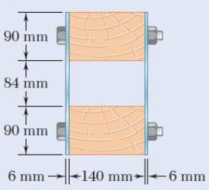
Fig. p6.56
(a)
The average shearing stress in the bolts.
Answer to Problem 56P
The average shearing stress in the bolts is
Explanation of Solution
Given information:
The diameter of the bolts is
The longitudinal spacing is
The beam is subjected to a vertical shear of
The modulus of elasticity for wood
The modulus of elasticity for steel
Calculation:
Consider the steel is to be the reference material. So modular ratio of steel is
Calculate the modular ratio of timber wood
Here,
Substitute
Total depth of the section d is as follows:
Calculate the moment of inertia for the symmetric section I as shown below.
Here, b is the width of the section and d is the depth of the section.
For steel:
For wood:
Calculate the moment of inertia for the transformed section as shown below.
Substitute 1 for
Calculate the first moment of area as shown below.
For wooden section:
Calculate the first moment of area for the transformed section Q as shown below.
Substitute
Calculate the horizontal shear per unit length q as shown below.
Here V is the vertical shear.
Substitute
Calculate the force acting on the bolt
Here, s is the longitudinal spacing.
Substitute
Calculate the area of bolt
Here,
Substitute
The bolt is subjected to double shear.
Calculate the shearing stress of the bolt
Substitute
Therefore, the average shearing stress in the bolts is
(b)
The shearing stress at the center of the cross section.
Answer to Problem 56P
The shearing stress at the center of the cross section is
Explanation of Solution
Given information:
The diameter of the bolts is
The longitudinal spacing is
The beam is subjected to a vertical shear of
The modulus of elasticity for wood
The modulus of elasticity for steel
Calculation:
Refer to part (a).
Moment of inertia for the transformed section
Calculate the first moment of area as shown below.
For the two steel plates:
Calculate the first moment of area along the neutral axis for the transformed section as shown below.
Substitute
Calculate the horizontal shear per unit length as shown below.
Substitute
Calculate the shearing stress as shown below.
Substitute
Therefore, the shearing stress at the center of the cross section is
Want to see more full solutions like this?
Chapter 6 Solutions
Mechanics of Materials, 7th Edition


- Three boards, each of 1.5 x3.5-in. rectangular cross section, are nailed together to form a beam that is subjected to a vertical shear of 250 lb. Knowing that the spacing between each pair of nails is 2.5 in., determine the shearing force in each nail.arrow_forwardTwo wooden planks, each 7/8 in thick and 6in wide, are joined by the glued mortise joint shown. Knowing that the wood used shears off along its grain when the average shearing stress reaches 120psi, determine the smallest allowable length d of the cuts if the joint is to withstand an axial load of magnitude P=1200-lb. Note: Seven surfaces carry the load, P=1200-lbarrow_forwardFor the beam and loading shown, consider section n–n and determine (a) the largest shearing stress in that section, (b) the shearing stress at point a.arrow_forward
- A) The four cross sections shown have different characteristics when subjected to a vertical shear force. Which of the four geometries shown has the largest value for the moment of the area, Q, about the neutral axis? B) Which of the four geometries shown has the smallest value for its moment of inertia about the x axis? C) Given that all four geometries are subjected to the same vertical shear force V, which of the four has the smallest value for the maximum shear stress?arrow_forwardTwo 20 × 100-mm and two 20 × 180-mm boards are glued together as shown to form a 120 × 200-mm box beam. Know that the beam is subjected to a vertical shear of 3.625 kN. Determine the average shearing stress in the glued joint at B.arrow_forwardFor the beam and loading shown, consider section n–n and determine the shearing stress at (a) point a, (b) point b.arrow_forward
- For the wide-flange beam with the loading shown, determine the largest load P that can be applied, knowing that the maximum normal stress is 160 MPa and the largest shearing stress is 100 MPa. W360 x 122 Barrow_forwardA 12-m simply supported overhang beam is supported at x = 0 and x = 10m. The overhanging portion is from x = 10m to x = 12m (the overhang portion is 2m). Two equal wheel loads of 20kN each, separated by 2m roll as a unit across the 12-m span. Determine the maximum shear developed in the span.arrow_forwardA beam consists of five planks of 1.5 x 6-in. cross section connected by steel bolts with a longitudinal spacing of 9 in. Knowing that the shear in the beam is vertical and equal to 2000 lb and that the allow-able average shearing stress in each bolt is 7500 psi, determine the smallest permissible bolt diameter that can be used.arrow_forward
- Two W8 x 31 rolled sections can be welded at A and B in either of the two ways shown in order to form a composite beam. Knowing that for each weld the allowable horizontal shearing force is 3000 lb per inch of weld, determine the maximum allowable vertical shear in the composite beam for each of the two arrangements shown.arrow_forwardThe thin-walled extruded beam shown is made of aluminum and has a uni-form 3-mm wall thickness. Knowing that the shear in the beam is 5 kN, deter-mine (a) the shearing stress at point A, (b) the maximum shearing stress in the beam. Note: The dimensions given are to lines midway between the outer and inner surfaces of the beam.arrow_forwardA steel tube having an outer diameter of 2.5 in. is used to transmit 9 hp when turning at 27 rev>min. Determine the inner diameter d of the tube to the nearest 1 8 in. if the allowable shear stress is tallow = 10 ksi.arrow_forward
 Elements Of ElectromagneticsMechanical EngineeringISBN:9780190698614Author:Sadiku, Matthew N. O.Publisher:Oxford University Press
 Mechanics of Materials (10th Edition)Mechanical EngineeringISBN:9780134319650Author:Russell C. HibbelerPublisher:PEARSON
 Thermodynamics: An Engineering ApproachMechanical EngineeringISBN:9781259822674Author:Yunus A. Cengel Dr., Michael A. BolesPublisher:McGraw-Hill Education
 Control Systems EngineeringMechanical EngineeringISBN:9781118170519Author:Norman S. NisePublisher:WILEY
 Mechanics of Materials (MindTap Course List)Mechanical EngineeringISBN:9781337093347Author:Barry J. Goodno, James M. GerePublisher:Cengage Learning
 Engineering Mechanics: StaticsMechanical EngineeringISBN:9781118807330Author:James L. Meriam, L. G. Kraige, J. N. BoltonPublisher:WILEY