Introductory Circuit Analysis (13th Edition)
13th Edition
ISBN: 9780133923605
Author: Robert L. Boylestad
Publisher: PEARSON
expand_more
expand_more
format_list_bulleted
Question

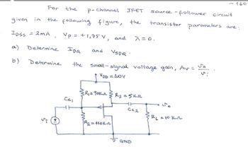
Transcribed Image Text:-160
For
the
P-channel
JFET
given in
the following figure,
the
IDSS = 2MA
a)
Determine
IDQ
and
VSDQ
b)
Determine
the
source-follower circuit
transistor parameters are:
Vp = +1,75 V, and λ=0.
Small-signal voltage gain, Av = So
VDD = 10V
R₁ = 90kr
Rs =5k
CC1
WW
R₂ = 110kn
50
C02
BL = 10 kr
GND
Expert Solution
This question has been solved!
Explore an expertly crafted, step-by-step solution for a thorough understanding of key concepts.
Step by stepSolved in 2 steps with 4 images

Knowledge Booster
Similar questions
- The transistor parameters for the circuit in Figure are B, =B2 = 100, VBE1on) = VBE2ton) = 0.7 V, and %3D VA1 =VA2 =0.Find the small signal voltage gain Av = vo/vs. (Note that V-=0.026 V) Vcc=9 V Rib Q1 Vs 1 ko -Ro 20 V 100 Q -wwarrow_forward........ (Figure-1) R. RB= 380kN,Rc= 1kN B = 100, VBB = Vcc=12V RB ww Vec CC ......... I, V CE СЕ V ВЕ BB Q-1-b) Describe briefly the input / output characteristics and application of Common Emitter BJT Configurationarrow_forwardDraw a n-p-n transistor connected in circuit common base (CB).Draw the input current-voltage characteristic, the output current-voltage characteristicsand the graph giving dependence of the output current as function of the input current.Define the amplification gain of this circuit.arrow_forward
- The DC Current Gain of a Transistor is Select one: a. Ratio of Collector Current to Base Current b. Ratio of Base Current to Collector Current c. Ratio of Emitter Current to Collector Current d. Ratio of Base Current to Emitter Currentarrow_forwardUsing LTSpice, simulate the circuit below, use 2N3904 for the transistor. Part ! DC simulation: Measure VCE and Ic. Use .op for the simulation cmd. Remove all capacitors and input signals first. Part 2 AC simulation: Connect all capacitors now and apply an AC signal at the input with an amplitufe of 1mV and a frequency of 1kHz. Determine the Voltage gain of the circuit by dividing Vo with Vin. Show the output for both the DC and AC analysis. Take a screenshot of the circuit and the output voltages and waveforms. Paste in a word file, write your answers, then save as pdf. 50 kΩ Σ 20 0,5 ΚΩ wwwh 9 Vcc=20 V Ca=1 µF = Cc₂ Cg=50 μF 5.6 kn B=100 Ca IST • 3.3 ΚΩ 5 ΚΩΣ CEarrow_forwardcircuits by using the small signal models of the transistor. Assume the Early voltage of the transistors are infinitely large. Calculate the small-signal input and output impedances of the following Vcc R1 R1 Rout VB RE Rin R2arrow_forward
- C. Draw a n-p-n transistor connected in circuit common emitter (CE). Draw the input current-voltage characteristic, the output current-voltage characteristics and the graph giving dependence of the output current as function of the input current. Define the amplification gain of this circuit.arrow_forwardQ1. (a) Consider the amplifier circuit in Figure Q1(a). Given the following: RI = 100 k2 R2 = 56 kN Rc =2 k2 Vcc = +8 V Assume the transistor has B = 100 and VBE(on) = 0.7 V. You may neglect Early effect and use VT = 26 mV. (i) Draw the DC equivalent circuit, then determine Iç and VCE. Draw the AC equivalent circuit using re model. Based on this, determine the parameters Av, Rin and Rout. (ii) Vcc Rc R1 R2 C3 Vout C2 Ci Vin Figure Q1(a)arrow_forwardOpen with v Consider class-A emitter follower circuit shown in the figure below. The circuit parameters are V+ = 24 V, V- = -24 V, and RL = 2000. The transistor parameters are B = 50, VBElon) = 0.7 V, and VCElsat) = 0.2 V. The output voltage is to vary between +20 V and -20 V. The minimum current in Q1 is to be ie1 = 20 mA. For vo = 0, find the power dissipated in the first transistor Q1- V+arrow_forward
- I need help pls. I will give thumbs uparrow_forwardConsider the circuit in Figure 2. The transistor has a parameter B that varies between 50 and 200. You want to know the operation of the circuit and the electrical variables at the end points. Calculate the following for B= 50 and B= 200. a) IE, VE and VB (Analysis in DC). b) The input resistance R." (Small signal analysis). c) The voltage gain VO/Vsing (Small signal analy). This 10 ΚΩ www o Rin 100 ΚΩ +3V +1₁ HH 1 ΚΩ 1₁ 1 ΚΩarrow_forwardPlease solve with work shown. Will upvotearrow_forward
arrow_back_ios
SEE MORE QUESTIONS
arrow_forward_ios
Recommended textbooks for you
 Introductory Circuit Analysis (13th Edition)Electrical EngineeringISBN:9780133923605Author:Robert L. BoylestadPublisher:PEARSON
 Delmar's Standard Textbook Of ElectricityElectrical EngineeringISBN:9781337900348Author:Stephen L. HermanPublisher:Cengage Learning
 Programmable Logic ControllersElectrical EngineeringISBN:9780073373843Author:Frank D. PetruzellaPublisher:McGraw-Hill Education
 Fundamentals of Electric CircuitsElectrical EngineeringISBN:9780078028229Author:Charles K Alexander, Matthew SadikuPublisher:McGraw-Hill Education
 Electric Circuits. (11th Edition)Electrical EngineeringISBN:9780134746968Author:James W. Nilsson, Susan RiedelPublisher:PEARSON
 Engineering ElectromagneticsElectrical EngineeringISBN:9780078028151Author:Hayt, William H. (william Hart), Jr, BUCK, John A.Publisher:Mcgraw-hill Education,

Introductory Circuit Analysis (13th Edition)
Electrical Engineering
ISBN:9780133923605
Author:Robert L. Boylestad
Publisher:PEARSON

Delmar's Standard Textbook Of Electricity
Electrical Engineering
ISBN:9781337900348
Author:Stephen L. Herman
Publisher:Cengage Learning

Programmable Logic Controllers
Electrical Engineering
ISBN:9780073373843
Author:Frank D. Petruzella
Publisher:McGraw-Hill Education

Fundamentals of Electric Circuits
Electrical Engineering
ISBN:9780078028229
Author:Charles K Alexander, Matthew Sadiku
Publisher:McGraw-Hill Education

Electric Circuits. (11th Edition)
Electrical Engineering
ISBN:9780134746968
Author:James W. Nilsson, Susan Riedel
Publisher:PEARSON

Engineering Electromagnetics
Electrical Engineering
ISBN:9780078028151
Author:Hayt, William H. (william Hart), Jr, BUCK, John A.
Publisher:Mcgraw-hill Education,