
Concept explainers
Videos
A dc source is connected to a series RLC circuit by a switch that closes at t = 0, as shown en Figure P4.61. The initial conditions are i(0 +) = 0 and
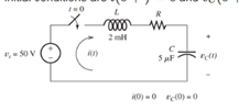
Figure P4.61
Want to see the full answer?
Check out a sample textbook solution
Chapter 4 Solutions
Electrical Engineering: Principles & Applications (7th Edition)
Additional Engineering Textbook Solutions
Electric machinery fundamentals
Basic Engineering Circuit Analysis
Fundamentals of Applied Electromagnetics (7th Edition)
Microelectronics: Circuit Analysis and Design
Electric Circuits (10th Edition)
Electric Circuits. (11th Edition)


- P4.42. The switch shown in Figure P4.42 has been closed for a long time prior to t=0, then it opens at t=0 and closes again at t=1 s. Find i L (t) for all t. 6H 121 Figure P4.42arrow_forward*P4.61. A dc source is connected to a series RLC circuit by a switch that closes at t = 0, as shown in Figure P4.61. The initial conditions are i(0+) = 0 and vc(0+) = 0. Write the dif- ferential equation for vc(t). Solve for vc(t) given that R = 80 2. t = 0 R 2 mH + V = 50 V i(t) vclt) 5 µF i(0) = 0 vc(0) = 0 Figure P4.61arrow_forward2. Find the differential equation to be solved by the following analog computer circuit. Resistors are in the order of MQ, capacitors are in the order of uf. So, start the solution with RC-1 acceptance. is the voltage at point C. (Make the solution in detail. Explain how the stress values at points A, B, D, E and F are found.) 0,5 ww 0,5 ww 12V Hit www me Darrow_forward
- Solve for Ij in the circuit shown in Figure P4.56. I= 102 -A j4 2arrow_forwardSolve for i(t) for t>0 in the circuit of Figure P4.67, with R=400 Ω, given that i( 0+ )=0 and v C ( 0+ )=20 V [Hint: Try a particular solution of the form i p ( t )= A cos( 100t )+B sin( 100t ).]arrow_forwardFind vout (t) for the circuit shown in Figure P4.60. | 102 mA Xz = 1 k2 Vout Xc = 10 k2arrow_forward
- For the circuit of Figure 2. Assuming that the capacitor voltage and inductor current are equal to zero at t = 0. a) Determine the expression for all the branch currents and capacitor voltage v(t) b) Obtain the plots of the branch currents and v(t) by creating a MATLAB model in Simulink. Verify the plots by using a MATLAB programarrow_forwardLearning Goal: To analyze an RC circuit to determine the initial voltage across a capacitor, then to find the step response of the capacitor voltage, and finally to find other circuit quantities, such as current, voltage, power, or energy. The step response of an RC circuit is the response of the capacitor voltage to a sudden application of a DC source. When the switching occurs, the capacitor stores or releases energy. (Figure 1) Figure R₁ R₂ www R3 b R4 ,t=0 1 of 1 R6 R5 ww Part D Write an expression for the capacitor voltage, v(t), for t > 0. Express your answer as an algebraic expression in terms of Vs, Is, R3, R5, R6, C. ► View Available Hint(s) v(t) = Submit Part E p(t) = ΑΣΦ Submit vec Write an expression for the power dissipated in the resistor R6 for t > 0+. Express your answer as an algebraic expression in terms of VS, Is, R3, R5, R6, and C. ► View Available Hint(s) V ΑΣΦ ? ↓↑ vec V ? mWarrow_forwardClosed loop poles in a second order system -3 + 4j and -3-4j If so, what is the damping rate of the system? 3/44/35/45/33/5one4/50arrow_forward
- solve Vc(s) using KCL at V1 and Vc(s). The answer I've been getting is (9030+900s)/(15s^2 +150s +10). Please verify if this is correct.arrow_forwardConsider the R-C circuit. we idealise the emf to be constant and have zero internal resistance. We begin with capacitor initially uncharged. At initial time t=0, the switch was closed. Answer the questions attached.arrow_forwardFor the circuit in Figure 3 the switch is in the left position for several minutes: (a) Find the Initlal voltage, V, on the capacitor just before the switch is flipped (b) Find an expression v(t) that describes the voltage across the 20 N resistor after the switch has been Figure 3 U 09 flipped to the right NOTE: Remember what we said in class: use a Circuit-Specific Equation to get a value you know. Then solve for whatever else the problem asks for +50 µF 380 0 20 2arrow_forward
 Introductory Circuit Analysis (13th Edition)Electrical EngineeringISBN:9780133923605Author:Robert L. BoylestadPublisher:PEARSON
 Delmar's Standard Textbook Of ElectricityElectrical EngineeringISBN:9781337900348Author:Stephen L. HermanPublisher:Cengage Learning
 Programmable Logic ControllersElectrical EngineeringISBN:9780073373843Author:Frank D. PetruzellaPublisher:McGraw-Hill Education
 Fundamentals of Electric CircuitsElectrical EngineeringISBN:9780078028229Author:Charles K Alexander, Matthew SadikuPublisher:McGraw-Hill Education
 Electric Circuits. (11th Edition)Electrical EngineeringISBN:9780134746968Author:James W. Nilsson, Susan RiedelPublisher:PEARSON
 Engineering ElectromagneticsElectrical EngineeringISBN:9780078028151Author:Hayt, William H. (william Hart), Jr, BUCK, John A.Publisher:Mcgraw-hill Education,