
Electrical Engineering: Principles & Applications (7th Edition)
7th Edition
ISBN: 9780134484143
Author: Allan R. Hambley
Publisher: PEARSON
expand_more
expand_more
format_list_bulleted
Videos
Textbook Question
Chapter 4, Problem 4.24P
The circuit shown in Figure P4.24 has been set up for a long time prior to t = 0 with the switch closed. Find the value of
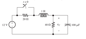
Figure P4.24
Expert Solution & Answer

Trending nowThis is a popular solution!

Learn your wayIncludes step-by-step video

schedule04:12
Students have asked these similar questions
For t < 0, the circuit shown in Figure P4.22 is at DC steady-state. The switch is thrown at t = 0
We know that the capacitor shown in Figure P4.11 is charged to a voltage of 10 V priorto t=0.a. Find expressions for the voltage across the capacitor vC(t) and the voltage across theresistor vR(t) for all time.b. Find an expression for the power delivered to the resistor.c. Integrate the power from t=0 to t=∞ to find the energy delivered.d. Show that the energy delivered to the resistor is equal to the energy stored in thecapacitor prior to t=0.
Consider the circuit shown in Figure P4.50. The initial current in the inductor is i s ( 0+)=0. Write the differential equation for i s(t) and solve. [Hint: Try a particular solution of the form i sp ( t )=A cos( 300t )+B sin( 300t ).]
Chapter 4 Solutions
Electrical Engineering: Principles & Applications (7th Edition)
Ch. 4 - Suppose we have a capacitance C discharging...Ch. 4 - The dielectric materials used in real capacitors...Ch. 4 - The initial voltage across the capacitor shown in...Ch. 4 - A 100F capacitance is initially charged to 1000 V....Ch. 4 - At t = 0, a charged 10{ F capacitance is connected...Ch. 4 - At time t1 , a capacitance C is charged to a...Ch. 4 - Given an initially charged capacitance that begins...Ch. 4 - The initial voltage across the capacitor shown in...Ch. 4 - In physics, the half-life is often used to...Ch. 4 - We know that a 50F capacitance is charged to an...
Ch. 4 - We know that the capacitor shown in Figure P4.11...Ch. 4 - The purchasing power P of a certain unit of...Ch. 4 - Derive an expression for vC(t) in the circuit of...Ch. 4 - Suppose that at t= 0, we connect an uncharged 10 F...Ch. 4 - Suppose we have a capacitance C that is charged to...Ch. 4 - A person shuffling across a dry carpet can be...Ch. 4 - Prob. 4.17PCh. 4 - Consider the circuit shown in Figure P4.18. Prior...Ch. 4 - List the steps for dc steady-state analysis of RLC...Ch. 4 - Explain why we replace capacitances with open...Ch. 4 - Solve for the steady-state values of i1, i2, and...Ch. 4 - Consider the circuit shown in Figure P4.22. What...Ch. 4 - In the circuit of Figure P4.23, the switch is in...Ch. 4 - The circuit shown in Figure P4.24 has been set up...Ch. 4 - Solve for the steady-state values of i1 , i2, i3,...Ch. 4 - The circuit shown in Figure P4.26 is operating in...Ch. 4 - Prob. 4.27PCh. 4 - Consider the circuit of Figure P4.28 in which the...Ch. 4 - For the circuit shown in Figure P4.29, the switch...Ch. 4 - Consider the circuit of Figure P4.30 in which the...Ch. 4 - Give the expression for the time constant of a...Ch. 4 - A circuit consists of switches that open or close...Ch. 4 - The circuit shown in Figure P4.33 is operating in...Ch. 4 - Consider the circuit shown in Figure P4.34. The...Ch. 4 - Repeat Problem P4.34 given iL(0)=0A .Ch. 4 - Real inductors have series resistance associated...Ch. 4 - Determine expressions for and sketch is(t) to...Ch. 4 - For the circuit shown in Figure P4.38,, find an...Ch. 4 - The circuit shown in Figure P4.39 is operating in...Ch. 4 - Consider the circuit shown in Figure P4.40. A...Ch. 4 - Due to components not shown in the figure, the...Ch. 4 - The switch shown in Figure P4.42 has been closed...Ch. 4 - Determine expressions for and sketch vR(t) to...Ch. 4 - What are the steps in solving a circuit having a...Ch. 4 - Prob. 4.45PCh. 4 - Solve for vC(t) for t > 0 in the circuit of Figure...Ch. 4 - Solve for v(t) for t > 0 in the circuit of Figure...Ch. 4 - Prob. 4.48PCh. 4 - Consider the circuit shown inFigure P4.49. The...Ch. 4 - Consider the circuit shown in Figure P4.50. The...Ch. 4 - The voltage source shown in Figure P4.51 is called...Ch. 4 - Determine the form of the particular solution for...Ch. 4 - Determine the form of the particular solution for...Ch. 4 - Prob. 4.54PCh. 4 - Prob. 4.55PCh. 4 - How can first-or second-order circuits be...Ch. 4 - Prob. 4.57PCh. 4 - Prob. 4.58PCh. 4 - Prob. 4.59PCh. 4 - Sketch a step response for a second-order system...Ch. 4 - A dc source is connected to a series RLC circuit...Ch. 4 - Repeat Problem P4.61 for R = 40 .Ch. 4 - Repeat Problem P4.61 for R = 20 .Ch. 4 - Prob. 4.64PCh. 4 - Repeat Problem P4.64 for R=50 .Ch. 4 - Repeat Problem P4.64 for R=500 .Ch. 4 - Solve for i(t) for t > 0 in the circuit of Figure...Ch. 4 - Prob. 4.68PCh. 4 - Prob. 4.69PCh. 4 - Prob. 4.70PCh. 4 - Use MATLAB to derive an expression for vc(t)in the...Ch. 4 - Prob. 4.72PCh. 4 - Consider the circuit shown in FigureP4.50 in which...Ch. 4 - Prob. 4.74PCh. 4 - Prob. 4.75PCh. 4 - Use MATLAB to solve for the mesh currents in the...Ch. 4 - The switch m the circuit shown in Figure T4.1 is...Ch. 4 - Prob. 4.2PTCh. 4 - Consider the circuit shown in Figure T4.3. Figure...Ch. 4 - Consider the circuit shown in Figure T4.4 in which...Ch. 4 - Write the MATLAB commands to obtain the solution...
Knowledge Booster


Learn more about
Need a deep-dive on the concept behind this application? Look no further. Learn more about this topic, electrical-engineering and related others by exploring similar questions and additional content below.Similar questions
- Consider the circuit shown in Figure P4.70. a. Write the differential equation for v(t). b. Find the damping coefficient, the natural frequency, and the form of the complementary solution. c. Usually, for a sinusoidal forcing function, we try a particular solution of the form v p ( t)=A cos( 10 4 t )+B sin( 10 4 t ). Why doesn’t that work in this case? d. Find the particular solution. [Hint: Try a particular solution of the form v p ( t)=At cos( 10 4 t )+B t sin( 10 4 t ). ] e. Find the complete solution for v(t).arrow_forwardConsider the circuit shown in Figure T4.3.a. Write the differential equation for i(t). b. Find the time constant and the form of the complementary solution. c. Find the particular solution. d. Find the complete solution for i(t).arrow_forwardDescribe the steady-state similarities and differences of DC and AC circuits with purelyresistive elementsarrow_forward
- When a switch is closed in a cirvuit containing a battery E,a resistance R and an inductance L,the current i build up at rate given by L di/dt +Ri=E.find "i" as a function "t"arrow_forwardThe circuit shown in Figure P4.39 is operating in steady state with the switch closed prior to t=0. Find expressions for i L ( t ) for t<0 and for t≥0. Sketch iL(t) to scale versus timearrow_forwardWhat is the practical application of a circuit that you can tune such that it reaches some minimum resistance? Would there be an application to being able to tune where that minimum occurs, by changing the capacitance or inductance of the circuit?arrow_forward
- P4.11. We know that the capacitor shown in Figure P4.11 O is charged to a voltage of 10 V prior to t a. Find expressions for the voltage across the capacitor vc(t) and the voltage across the resistor vR(t) for all time. b. Find an expression for the power delivered to the resistor. c. Integrate the power from t = 0 to t = ∞ to find the energy delivered. 0. d. Show that the energy delivered to the resistor is equal to the energy stored in the capacitor prior to t = 0. t = 0 R = 100 N 100 μF UR(1)arrow_forwardP4.30. Consider the circuit of Figure P4.30 in which the switch has been closed for a long time prior to t=0. Determine the values of v C (t) before t=0 and a long time after t=0. Also, determine the time constant after the switch opens and expressions for v C (t). Sketch v C (t) to scale versus time for -4sts16 s. 2 MA 30 V 2 uF I MO Figure P4.30arrow_forwardWrite the differential equation for i L(t) and find the complete solution for the circuit of Figure P4.45. [Hint: Try a particular solution of the form i Lp ( t )=A e −t .]arrow_forward
- Title Find the capacitor voltage in the network shown in Figure P4.2 if the switch closes at t = 0. Assume Description Find the capacitor voltage in the network shown in Figure P4.2 if the switch closes at t = 0. Assume zero initial conditions. Also find the time constant, rise time, and settling time for the capacitor voltage. /=0) W 1.802 0.79 F FIGURE P4.2 Plot the step response for Problem 4 using MATLAB. From your plots, find the time constant, rise time, and settling timearrow_forwardFor the circuit shown in Figure P4.29, the switch is closed for a long time prior to t=0.Find expressions for vC(t) and sketch it to scale for −80≤t≤160 ms.arrow_forwardThe switch shown in Figure P4.42 has been closed for a long time prior to t=0, then it opens at t=0 and closes again at t=1s. Find i L (t) for all t.arrow_forward
arrow_back_ios
SEE MORE QUESTIONS
arrow_forward_ios
Recommended textbooks for you
 Introductory Circuit Analysis (13th Edition)Electrical EngineeringISBN:9780133923605Author:Robert L. BoylestadPublisher:PEARSON
 Delmar's Standard Textbook Of ElectricityElectrical EngineeringISBN:9781337900348Author:Stephen L. HermanPublisher:Cengage Learning
 Programmable Logic ControllersElectrical EngineeringISBN:9780073373843Author:Frank D. PetruzellaPublisher:McGraw-Hill Education
 Fundamentals of Electric CircuitsElectrical EngineeringISBN:9780078028229Author:Charles K Alexander, Matthew SadikuPublisher:McGraw-Hill Education
 Electric Circuits. (11th Edition)Electrical EngineeringISBN:9780134746968Author:James W. Nilsson, Susan RiedelPublisher:PEARSON
 Engineering ElectromagneticsElectrical EngineeringISBN:9780078028151Author:Hayt, William H. (william Hart), Jr, BUCK, John A.Publisher:Mcgraw-hill Education,
Introductory Circuit Analysis (13th Edition)
Electrical Engineering
ISBN:9780133923605
Author:Robert L. Boylestad
Publisher:PEARSON
Delmar's Standard Textbook Of Electricity
Electrical Engineering
ISBN:9781337900348
Author:Stephen L. Herman
Publisher:Cengage Learning
Programmable Logic Controllers
Electrical Engineering
ISBN:9780073373843
Author:Frank D. Petruzella
Publisher:McGraw-Hill Education
Fundamentals of Electric Circuits
Electrical Engineering
ISBN:9780078028229
Author:Charles K Alexander, Matthew Sadiku
Publisher:McGraw-Hill Education
Electric Circuits. (11th Edition)
Electrical Engineering
ISBN:9780134746968
Author:James W. Nilsson, Susan Riedel
Publisher:PEARSON
Engineering Electromagnetics
Electrical Engineering
ISBN:9780078028151
Author:Hayt, William H. (william Hart), Jr, BUCK, John A.
Publisher:Mcgraw-hill Education,
ECE320 Lecture1-3c: Steady-State Error, System Type; Author: Rose-Hulman Online;https://www.youtube.com/watch?v=hG7dq-51AAg;License: Standard Youtube License