
Electrical Engineering: Principles & Applications (7th Edition)
7th Edition
ISBN: 9780134484143
Author: Allan R. Hambley
Publisher: PEARSON
expand_more
expand_more
format_list_bulleted
Videos
Textbook Question
Chapter 4, Problem 4.23P
In the circuit of Figure P4.23, the switch is in position A for a long time prior to
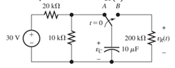
Figure P4.23
Expert Solution & Answer
Want to see the full answer?
Check out a sample textbook solution
Students have asked these similar questions
For the circuit shown in Figure P4.29, the switch is closed for a long time prior to t=0.Find expressions for vC(t) and sketch it to scale for −80≤t≤160 ms.
P4.30. Consider the circuit of Figure P4.30 in which the switch has been closed for a long time
prior to t=0. Determine the values of v C (t) before t=0 and a long time after t=0. Also,
determine the time constant after the switch opens and expressions for v C (t). Sketch v C (t)
to scale versus time for -4sts16 s.
2 MA
30 V
2 uF
I MO
Figure P4.30
In the circuit shown in Figure P4.a, the switch is closed at t = 0. The capacitor voltage is charged to
vc (0) = 12 V prior to t = 0. The voltage source is us(t) = 35 cos (1000t) V. Find the expressions of uc (t)
and ic(t), respectively.
vs(t)
500 Ω
ww
t=0
+ v (t) -
HH
i(t) 1.5 µF
300 Ω
Chapter 4 Solutions
Electrical Engineering: Principles & Applications (7th Edition)
Ch. 4 - Suppose we have a capacitance C discharging...Ch. 4 - The dielectric materials used in real capacitors...Ch. 4 - The initial voltage across the capacitor shown in...Ch. 4 - A 100F capacitance is initially charged to 1000 V....Ch. 4 - At t = 0, a charged 10{ F capacitance is connected...Ch. 4 - At time t1 , a capacitance C is charged to a...Ch. 4 - Given an initially charged capacitance that begins...Ch. 4 - The initial voltage across the capacitor shown in...Ch. 4 - In physics, the half-life is often used to...Ch. 4 - We know that a 50F capacitance is charged to an...
Ch. 4 - We know that the capacitor shown in Figure P4.11...Ch. 4 - The purchasing power P of a certain unit of...Ch. 4 - Derive an expression for vC(t) in the circuit of...Ch. 4 - Suppose that at t= 0, we connect an uncharged 10 F...Ch. 4 - Suppose we have a capacitance C that is charged to...Ch. 4 - A person shuffling across a dry carpet can be...Ch. 4 - Prob. 4.17PCh. 4 - Consider the circuit shown in Figure P4.18. Prior...Ch. 4 - List the steps for dc steady-state analysis of RLC...Ch. 4 - Explain why we replace capacitances with open...Ch. 4 - Solve for the steady-state values of i1, i2, and...Ch. 4 - Consider the circuit shown in Figure P4.22. What...Ch. 4 - In the circuit of Figure P4.23, the switch is in...Ch. 4 - The circuit shown in Figure P4.24 has been set up...Ch. 4 - Solve for the steady-state values of i1 , i2, i3,...Ch. 4 - The circuit shown in Figure P4.26 is operating in...Ch. 4 - Prob. 4.27PCh. 4 - Consider the circuit of Figure P4.28 in which the...Ch. 4 - For the circuit shown in Figure P4.29, the switch...Ch. 4 - Consider the circuit of Figure P4.30 in which the...Ch. 4 - Give the expression for the time constant of a...Ch. 4 - A circuit consists of switches that open or close...Ch. 4 - The circuit shown in Figure P4.33 is operating in...Ch. 4 - Consider the circuit shown in Figure P4.34. The...Ch. 4 - Repeat Problem P4.34 given iL(0)=0A .Ch. 4 - Real inductors have series resistance associated...Ch. 4 - Determine expressions for and sketch is(t) to...Ch. 4 - For the circuit shown in Figure P4.38,, find an...Ch. 4 - The circuit shown in Figure P4.39 is operating in...Ch. 4 - Consider the circuit shown in Figure P4.40. A...Ch. 4 - Due to components not shown in the figure, the...Ch. 4 - The switch shown in Figure P4.42 has been closed...Ch. 4 - Determine expressions for and sketch vR(t) to...Ch. 4 - What are the steps in solving a circuit having a...Ch. 4 - Prob. 4.45PCh. 4 - Solve for vC(t) for t > 0 in the circuit of Figure...Ch. 4 - Solve for v(t) for t > 0 in the circuit of Figure...Ch. 4 - Prob. 4.48PCh. 4 - Consider the circuit shown inFigure P4.49. The...Ch. 4 - Consider the circuit shown in Figure P4.50. The...Ch. 4 - The voltage source shown in Figure P4.51 is called...Ch. 4 - Determine the form of the particular solution for...Ch. 4 - Determine the form of the particular solution for...Ch. 4 - Prob. 4.54PCh. 4 - Prob. 4.55PCh. 4 - How can first-or second-order circuits be...Ch. 4 - Prob. 4.57PCh. 4 - Prob. 4.58PCh. 4 - Prob. 4.59PCh. 4 - Sketch a step response for a second-order system...Ch. 4 - A dc source is connected to a series RLC circuit...Ch. 4 - Repeat Problem P4.61 for R = 40 .Ch. 4 - Repeat Problem P4.61 for R = 20 .Ch. 4 - Prob. 4.64PCh. 4 - Repeat Problem P4.64 for R=50 .Ch. 4 - Repeat Problem P4.64 for R=500 .Ch. 4 - Solve for i(t) for t > 0 in the circuit of Figure...Ch. 4 - Prob. 4.68PCh. 4 - Prob. 4.69PCh. 4 - Prob. 4.70PCh. 4 - Use MATLAB to derive an expression for vc(t)in the...Ch. 4 - Prob. 4.72PCh. 4 - Consider the circuit shown in FigureP4.50 in which...Ch. 4 - Prob. 4.74PCh. 4 - Prob. 4.75PCh. 4 - Use MATLAB to solve for the mesh currents in the...Ch. 4 - The switch m the circuit shown in Figure T4.1 is...Ch. 4 - Prob. 4.2PTCh. 4 - Consider the circuit shown in Figure T4.3. Figure...Ch. 4 - Consider the circuit shown in Figure T4.4 in which...Ch. 4 - Write the MATLAB commands to obtain the solution...
Knowledge Booster


Learn more about
Need a deep-dive on the concept behind this application? Look no further. Learn more about this topic, electrical-engineering and related others by exploring similar questions and additional content below.Similar questions
- Solve for i(t) for t>0 in the circuit of Figure P4.67, with R=400 Ω, given that i( 0+ )=0 and v C ( 0+ )=20 V [Hint: Try a particular solution of the form i p ( t )= A cos( 100t )+B sin( 100t ).]arrow_forwardP4.45.) Write the differential equation for i(t) and find the complete solution for the circuit of Figure P4.45. [Hint: Try a particular solution of the form ip (t) = Ae- ]with out Lapluce t = 0 10 H i(t) 5e Figure P4.45arrow_forwardi find in other explain to this that the answer is Vc+4i(x). ,,,,, but why it's not VL + Vc + 4i(x) explain the answer pleasearrow_forward
- The switch shown in Figure P4.42 has been closed for a long time prior to t=0, then it opens at t=0 and closes again at t=1s. Find i L (t) for all t.arrow_forwardIn the circuit of Figure P4.23, the switch is in position A for a long time prior to t=0. Findexpressions for vR(t) and sketch it to scale for -2≤t≤10 s.arrow_forwardFind vout (t) for the circuit shown in Figure P4.60. | 102 mA Xz = 1 k2 Vout Xc = 10 k2arrow_forward
- Solve for i L ( t ) for t>0 in the circuit of Figure P4.48. You will need to make an educated guess as to the form of the particular solution. [Hint: The particular solution includes terms with the same functional forms as the terms found in the forcing function and its derivatives.]arrow_forwardFor the circuit of Figure 2. Assuming that the capacitor voltage and inductor current are equal to zero at t = 0. a) Determine the expression for all the branch currents and capacitor voltage v(t) b) Obtain the plots of the branch currents and v(t) by creating a MATLAB model in Simulink. Verify the plots by using a MATLAB programarrow_forwardQ4. Consider the circuit of Figure Q4 with Is(t)= 3u(t) V, (a) Obtain VF(t) and i(t) for t>0 in the circuit (b) If Is(t) = 30u(t), determine VF(t) and i(t) for t>0 in the circuit (c) Compare the results (a) and (b). Explain and write the conclusion from the results (c). Is A 5Ω ww 5H M 292 Figure Q4 1Ω v(t) 20 (V) + 0.2Farrow_forward
- An LR circuit includes a resistor of resistance R, an inductor of inductance L and a battery of emf E = 10 V. At time t = 0 the current in the circuit is I = 0. At time t = 6.1 ms the current is I = 0.66 A. What are the values of L and R?arrow_forwardA dc source is connected to a series RLC circuit by a switch that closes at t=0, as shownin Figure P4.61. The initial conditions are i(0+)=0 and vC(0+)=0. Write the differentialequation for vC(t).Solve for v C ( t ), if R = 80 Ω.arrow_forwardDescribe and solve the following differential equation: y"-4y' + 3y = x²-2x+1arrow_forward
arrow_back_ios
SEE MORE QUESTIONS
arrow_forward_ios
Recommended textbooks for you
 Introductory Circuit Analysis (13th Edition)Electrical EngineeringISBN:9780133923605Author:Robert L. BoylestadPublisher:PEARSON
 Delmar's Standard Textbook Of ElectricityElectrical EngineeringISBN:9781337900348Author:Stephen L. HermanPublisher:Cengage Learning
 Programmable Logic ControllersElectrical EngineeringISBN:9780073373843Author:Frank D. PetruzellaPublisher:McGraw-Hill Education
 Fundamentals of Electric CircuitsElectrical EngineeringISBN:9780078028229Author:Charles K Alexander, Matthew SadikuPublisher:McGraw-Hill Education
 Electric Circuits. (11th Edition)Electrical EngineeringISBN:9780134746968Author:James W. Nilsson, Susan RiedelPublisher:PEARSON
 Engineering ElectromagneticsElectrical EngineeringISBN:9780078028151Author:Hayt, William H. (william Hart), Jr, BUCK, John A.Publisher:Mcgraw-hill Education,
Introductory Circuit Analysis (13th Edition)
Electrical Engineering
ISBN:9780133923605
Author:Robert L. Boylestad
Publisher:PEARSON
Delmar's Standard Textbook Of Electricity
Electrical Engineering
ISBN:9781337900348
Author:Stephen L. Herman
Publisher:Cengage Learning
Programmable Logic Controllers
Electrical Engineering
ISBN:9780073373843
Author:Frank D. Petruzella
Publisher:McGraw-Hill Education
Fundamentals of Electric Circuits
Electrical Engineering
ISBN:9780078028229
Author:Charles K Alexander, Matthew Sadiku
Publisher:McGraw-Hill Education
Electric Circuits. (11th Edition)
Electrical Engineering
ISBN:9780134746968
Author:James W. Nilsson, Susan Riedel
Publisher:PEARSON
Engineering Electromagnetics
Electrical Engineering
ISBN:9780078028151
Author:Hayt, William H. (william Hart), Jr, BUCK, John A.
Publisher:Mcgraw-hill Education,
ECE320 Lecture1-3c: Steady-State Error, System Type; Author: Rose-Hulman Online;https://www.youtube.com/watch?v=hG7dq-51AAg;License: Standard Youtube License