
Introductory Circuit Analysis (13th Edition)
13th Edition
ISBN: 9780133923605
Author: Robert L. Boylestad
Publisher: PEARSON
expand_more
expand_more
format_list_bulleted
Related questions
Question
thumb_up100%

Transcribed Image Text:**Educational Content on Circuit Analysis**
---
**Circuit Description and Analysis**
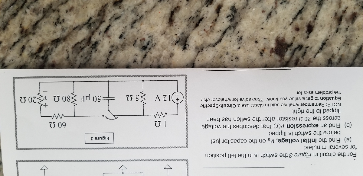
In this section, we will analyze the circuit depicted in Figure 3. The circuit consists of several resistors, a capacitor, and a voltage source. Let’s examine each component and their configuration:
### Circuit Diagram Description
- **Components:**
- A 12V voltage source
- Resistors: 12Ω, 20Ω, 80Ω, 5Ω, and 60Ω
- A 50μF capacitor
- A switch that can be opened or closed
- **Configuration:**
- The 12Ω and 20Ω resistors are connected in parallel.
- The resulting parallel combination is connected in series with an 80Ω resistor.
- This series combination is then connected in parallel with a 50μF capacitor.
- Finally, this is connected in series with a 5Ω resistor and the 12V voltage source.
### Analysis Tasks
1. **Find the Initial Voltage (v0):**
- Determine the initial voltage on the capacitor just before the switch is flipped.
2. **Find an Expression (v(t)):**
- Develop an expression that describes the voltage across the 20Ω resistor after the switch has been altered, allowing the circuit to reach a new state.
3. **Use Circuit-Specific Equations:**
- Apply circuit-specific equations to get a value you can verify. Use this as a problem-solving strategy for various numerical exercises.
Remember, solving these steps will help you understand how circuits respond to changes and provide insight into their dynamic behavior.
---
Expert Solution
This question has been solved!
Explore an expertly crafted, step-by-step solution for a thorough understanding of key concepts.

This is a popular solution

Trending nowThis is a popular solution!

Step by stepSolved in 2 steps with 3 images

Knowledge Booster


Learn more about
Need a deep-dive on the concept behind this application? Look no further. Learn more about this topic, electrical-engineering and related others by exploring similar questions and additional content below.Similar questions
- PLEASE LABEL AND DESCRIBE DIAGRAMarrow_forwardA circuit is comprised of an inductor, a capacitor, a battery and a switch. When a he switch is in position "a", the battery is in series with the capacitor, but the inductor is excluded. When the switch is in position "b", the capacitor and the inductor are in series, but the battery is excluded. Two voltmeters and an ammeter have been added to the circuit, as shown. Vc VL Vo > A 8% Part (a) Initially the switch is moved to position "a" where it remains until the capacitor attains its maximum charge. Enter an expression for the maximum charge on the capacitor. Inax = - A 8% Part (b) Once the capacitor is fully charged, the switch is moved from position "a" to position "b". Let q represent the charge on the capacitor, and et I represent the current measured by the ammeter at any given time after the switch is moved to position "b". Enter an expression for a Kirchhoff Loop Rule quation for the circuit that now includes both the capacitor and the inductor. -A 8% Part (c) Current is the…arrow_forwardFour 2H inductors are connected in parallel. What is the equivalent inductance?arrow_forward
- Please help plot the voltage waveforms across the capacitor and resistor.arrow_forwardThe circuit is in continuity mode before the switch is opened. What is the initial voltage of the capacitor Uco before opening the switch. I Select one: O a. Uco = 0 O b. Uco = RI O c. Uco=E O d. Uco= E R karrow_forwardion e Select the value of C to produce the desired total capacitance of C+=2μµF in the circuit. CT O a. 6 uF O b. 12 uF O c. 5/3 uF O d. O e. C₁-2μF 3 uF None of them HE C C₂-4uFarrow_forward
- Three capacitors 10 µF, 20 µF, 30 μF are connected in series across 150V (sinusoidal). Then identify the correct statement Maximum voltage will be applied across 10 µF Maximum voltage will be applied across 30 µF Maximum voltage will be applied across 20 µF Minimum voltage will be applied across 10 µFarrow_forwardA sinewave voltage with amplitude 2 V and frequency 1 kHz is applied capacitor. The capacitance is 0.1 uF. What is the amplitude of the current? across aarrow_forwardA 30-mF capacitor is connected into a 240-V, 60-Hz circuit. What is the current flow in this circuit?arrow_forward
arrow_back_ios
arrow_forward_ios
Recommended textbooks for you
- Introductory Circuit Analysis (13th Edition)Electrical EngineeringISBN:9780133923605Author:Robert L. BoylestadPublisher:PEARSON
 Delmar's Standard Textbook Of ElectricityElectrical EngineeringISBN:9781337900348Author:Stephen L. HermanPublisher:Cengage Learning
 Programmable Logic ControllersElectrical EngineeringISBN:9780073373843Author:Frank D. PetruzellaPublisher:McGraw-Hill Education
  Fundamentals of Electric CircuitsElectrical EngineeringISBN:9780078028229Author:Charles K Alexander, Matthew SadikuPublisher:McGraw-Hill Education
 Electric Circuits. (11th Edition)Electrical EngineeringISBN:9780134746968Author:James W. Nilsson, Susan RiedelPublisher:PEARSON
 Engineering ElectromagneticsElectrical EngineeringISBN:9780078028151Author:Hayt, William H. (william Hart), Jr, BUCK, John A.Publisher:Mcgraw-hill Education,
Introductory Circuit Analysis (13th Edition)
Electrical Engineering
ISBN:9780133923605
Author:Robert L. Boylestad
Publisher:PEARSON
Delmar's Standard Textbook Of Electricity
Electrical Engineering
ISBN:9781337900348
Author:Stephen L. Herman
Publisher:Cengage Learning
Programmable Logic Controllers
Electrical Engineering
ISBN:9780073373843
Author:Frank D. Petruzella
Publisher:McGraw-Hill Education
Fundamentals of Electric Circuits
Electrical Engineering
ISBN:9780078028229
Author:Charles K Alexander, Matthew Sadiku
Publisher:McGraw-Hill Education
Electric Circuits. (11th Edition)
Electrical Engineering
ISBN:9780134746968
Author:James W. Nilsson, Susan Riedel
Publisher:PEARSON
Engineering Electromagnetics
Electrical Engineering
ISBN:9780078028151
Author:Hayt, William H. (william Hart), Jr, BUCK, John A.
Publisher:Mcgraw-hill Education,