
Electrical Engineering: Principles & Applications (7th Edition)
7th Edition
ISBN: 9780134484143
Author: Allan R. Hambley
Publisher: PEARSON
expand_more
expand_more
format_list_bulleted
Concept explainers
Videos
Textbook Question
Chapter 4, Problem 4.34P
Consider the circuit shown in Figure P4.34. The initial current in the inductor is
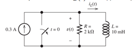
Figure P4.34
Expert Solution & Answer
Want to see the full answer?
Check out a sample textbook solution
Students have asked these similar questions
*P4.34. Consider the circuit shown in Figure P4.34. The initial current in the inductor is i L (0-
)= -0.2 A. Find expressions for i L (t) and v() for t20 and sketch to scale versus time.
R=
2 kl
L=
0.3 A
10 mH
Figure P4.34
The initial capacitor voltage is 4 V. Switch S1 is closed at t = 0. The charge (in micro C) lost by the capacitor form t = 25 microS to t = 100 microS is:1) 6.992) 8.713) 5.554) 10Please show detailed steps and work
Solve for v(t) for t>0 in the circuit of Figure P4.47, given that the inductor current is zero prior to t=0. [Hint: Try a particular solution of the form v p =A cos( 10t )+B sin( 10t ).]
Chapter 4 Solutions
Electrical Engineering: Principles & Applications (7th Edition)
Ch. 4 - Suppose we have a capacitance C discharging...Ch. 4 - The dielectric materials used in real capacitors...Ch. 4 - The initial voltage across the capacitor shown in...Ch. 4 - A 100F capacitance is initially charged to 1000 V....Ch. 4 - At t = 0, a charged 10{ F capacitance is connected...Ch. 4 - At time t1 , a capacitance C is charged to a...Ch. 4 - Given an initially charged capacitance that begins...Ch. 4 - The initial voltage across the capacitor shown in...Ch. 4 - In physics, the half-life is often used to...Ch. 4 - We know that a 50F capacitance is charged to an...
Ch. 4 - We know that the capacitor shown in Figure P4.11...Ch. 4 - The purchasing power P of a certain unit of...Ch. 4 - Derive an expression for vC(t) in the circuit of...Ch. 4 - Suppose that at t= 0, we connect an uncharged 10 F...Ch. 4 - Suppose we have a capacitance C that is charged to...Ch. 4 - A person shuffling across a dry carpet can be...Ch. 4 - Prob. 4.17PCh. 4 - Consider the circuit shown in Figure P4.18. Prior...Ch. 4 - List the steps for dc steady-state analysis of RLC...Ch. 4 - Explain why we replace capacitances with open...Ch. 4 - Solve for the steady-state values of i1, i2, and...Ch. 4 - Consider the circuit shown in Figure P4.22. What...Ch. 4 - In the circuit of Figure P4.23, the switch is in...Ch. 4 - The circuit shown in Figure P4.24 has been set up...Ch. 4 - Solve for the steady-state values of i1 , i2, i3,...Ch. 4 - The circuit shown in Figure P4.26 is operating in...Ch. 4 - Prob. 4.27PCh. 4 - Consider the circuit of Figure P4.28 in which the...Ch. 4 - For the circuit shown in Figure P4.29, the switch...Ch. 4 - Consider the circuit of Figure P4.30 in which the...Ch. 4 - Give the expression for the time constant of a...Ch. 4 - A circuit consists of switches that open or close...Ch. 4 - The circuit shown in Figure P4.33 is operating in...Ch. 4 - Consider the circuit shown in Figure P4.34. The...Ch. 4 - Repeat Problem P4.34 given iL(0)=0A .Ch. 4 - Real inductors have series resistance associated...Ch. 4 - Determine expressions for and sketch is(t) to...Ch. 4 - For the circuit shown in Figure P4.38,, find an...Ch. 4 - The circuit shown in Figure P4.39 is operating in...Ch. 4 - Consider the circuit shown in Figure P4.40. A...Ch. 4 - Due to components not shown in the figure, the...Ch. 4 - The switch shown in Figure P4.42 has been closed...Ch. 4 - Determine expressions for and sketch vR(t) to...Ch. 4 - What are the steps in solving a circuit having a...Ch. 4 - Prob. 4.45PCh. 4 - Solve for vC(t) for t > 0 in the circuit of Figure...Ch. 4 - Solve for v(t) for t > 0 in the circuit of Figure...Ch. 4 - Prob. 4.48PCh. 4 - Consider the circuit shown inFigure P4.49. The...Ch. 4 - Consider the circuit shown in Figure P4.50. The...Ch. 4 - The voltage source shown in Figure P4.51 is called...Ch. 4 - Determine the form of the particular solution for...Ch. 4 - Determine the form of the particular solution for...Ch. 4 - Prob. 4.54PCh. 4 - Prob. 4.55PCh. 4 - How can first-or second-order circuits be...Ch. 4 - Prob. 4.57PCh. 4 - Prob. 4.58PCh. 4 - Prob. 4.59PCh. 4 - Sketch a step response for a second-order system...Ch. 4 - A dc source is connected to a series RLC circuit...Ch. 4 - Repeat Problem P4.61 for R = 40 .Ch. 4 - Repeat Problem P4.61 for R = 20 .Ch. 4 - Prob. 4.64PCh. 4 - Repeat Problem P4.64 for R=50 .Ch. 4 - Repeat Problem P4.64 for R=500 .Ch. 4 - Solve for i(t) for t > 0 in the circuit of Figure...Ch. 4 - Prob. 4.68PCh. 4 - Prob. 4.69PCh. 4 - Prob. 4.70PCh. 4 - Use MATLAB to derive an expression for vc(t)in the...Ch. 4 - Prob. 4.72PCh. 4 - Consider the circuit shown in FigureP4.50 in which...Ch. 4 - Prob. 4.74PCh. 4 - Prob. 4.75PCh. 4 - Use MATLAB to solve for the mesh currents in the...Ch. 4 - The switch m the circuit shown in Figure T4.1 is...Ch. 4 - Prob. 4.2PTCh. 4 - Consider the circuit shown in Figure T4.3. Figure...Ch. 4 - Consider the circuit shown in Figure T4.4 in which...Ch. 4 - Write the MATLAB commands to obtain the solution...
Knowledge Booster


Learn more about
Need a deep-dive on the concept behind this application? Look no further. Learn more about this topic, electrical-engineering and related others by exploring similar questions and additional content below.Similar questions
- The capacitor behaves as an open circuit to a DC source. Why? How does the inductor behave to a DC source? Please explain in great detail.arrow_forwardP4.34. Consider the circuit shown in Figure P4.34. The initial current in the inductor is iL (0-) 0. Find expressions for i (t) and v(t) for t> 0 and sketch to scale versus time. 0.1 A (1) R = v(t) 1 k2 t = 0 1 mH Figure P4.34arrow_forwardWhen a switch is closed in a cirvuit containing a battery E,a resistance R and an inductance L,the current i build up at rate given by L di/dt +Ri=E.find "i" as a function "t"arrow_forward
- The circuit shown in Figure P4.39 is operating in steady state with the switch closed prior to t=0. Find expressions for i L ( t ) for t<0 and for t≥0. Sketch iL(t) to scale versus timearrow_forwardDerive the equivalent circuit for a parallel connection of ideal capacitors. Assume that the initial voltage across the paralleled capacitors is v(t0). (Hint: Sum the currents into the string of capacitors, recognizing that the parallel connection forces the voltage across each capacitor to be the same.)arrow_forward4.4 25 25. A capacitor (0.02 F) is charged to 1 V and then connected in series with an inductor (10 H) and a resistor (40 S2). Ini- tially, there is no current in the circuit. Find the amplitude, frequency, and phase of the charge on the capacitor and plot its graph.arrow_forward
- For the circuit in the figure, initially the switch S is closed in (b), until the capacitor is charged; then the switch goes to point (a) so that the battery is disconnected and the capacitor, resistor and inductor are connected in series. Once S is connected at point (a), find a) the angular frequency of oscillation for the series circuit b) write the equation for the charge on the capacitor as a function of time with the respective values of Qmax, angular frequency Wd and time T c) make the Q(t) graph showing explicitly the envelope of the exponential decay (Hint: use geogebra or an application of your choice to obtain a graph).arrow_forwardP4.44. What are the steps in solving a circuit having a resistance, a source, and an inductance (or capacitance)? *P4.45.) Write the differential equation for i(t) and find the complete solution for the circuit of Figure P4.45. [Hint: Try a particular solution of the form ip(t) =Ae-!] %3D 10 H 5et i(t) 5Ω Figure P4.45 P14arrow_forwardGiven circuit below, use superposition to find voltage across the capacitor, vclt). Frequency is 100 Hz. 6kn 4kn reee zkn O SmA <45 Vc (t) DC a) Given circuit below and switch ciosed for long time, what is the value of Vc? 5mA 3 luk bị At0, switch is opened. Write a mathematical expression for Velt) after opening of the switch. Evaluate this voltage at te10 ms. Attach File Browse Local Fies rowie Conent Cotection 74°Farrow_forward
- The circuit shown consists of four capacitors, an ideal battery of emf &, a switch 'S' and an inductor of inductance L. The switch Sis kept open for a long time. Find the maximum current through the inductor after the switch 'S' is closed. 2C 4C C S 8 3C =8arrow_forwardSolve the circuit by obtaining the state equation. The initial condition voltage value of the capacitance element is VC (0) = 1Volt. R1 = R2 = R3 = R4 = 1Ω, E = 3Volt. State the core solution and the forced solution components in the solution you obtained.arrow_forwardDERIVE FOR INDUCTOR VOLTAGE ONLY, DO NOT CONCERN YOURSELF WITH THE MATLAB PARTS, I CAN DO THAT ON MY OWN.arrow_forward
arrow_back_ios
SEE MORE QUESTIONS
arrow_forward_ios
Recommended textbooks for you
 Introductory Circuit Analysis (13th Edition)Electrical EngineeringISBN:9780133923605Author:Robert L. BoylestadPublisher:PEARSON
 Delmar's Standard Textbook Of ElectricityElectrical EngineeringISBN:9781337900348Author:Stephen L. HermanPublisher:Cengage Learning
 Programmable Logic ControllersElectrical EngineeringISBN:9780073373843Author:Frank D. PetruzellaPublisher:McGraw-Hill Education
 Fundamentals of Electric CircuitsElectrical EngineeringISBN:9780078028229Author:Charles K Alexander, Matthew SadikuPublisher:McGraw-Hill Education
 Electric Circuits. (11th Edition)Electrical EngineeringISBN:9780134746968Author:James W. Nilsson, Susan RiedelPublisher:PEARSON
 Engineering ElectromagneticsElectrical EngineeringISBN:9780078028151Author:Hayt, William H. (william Hart), Jr, BUCK, John A.Publisher:Mcgraw-hill Education,
Introductory Circuit Analysis (13th Edition)
Electrical Engineering
ISBN:9780133923605
Author:Robert L. Boylestad
Publisher:PEARSON
Delmar's Standard Textbook Of Electricity
Electrical Engineering
ISBN:9781337900348
Author:Stephen L. Herman
Publisher:Cengage Learning
Programmable Logic Controllers
Electrical Engineering
ISBN:9780073373843
Author:Frank D. Petruzella
Publisher:McGraw-Hill Education
Fundamentals of Electric Circuits
Electrical Engineering
ISBN:9780078028229
Author:Charles K Alexander, Matthew Sadiku
Publisher:McGraw-Hill Education
Electric Circuits. (11th Edition)
Electrical Engineering
ISBN:9780134746968
Author:James W. Nilsson, Susan Riedel
Publisher:PEARSON
Engineering Electromagnetics
Electrical Engineering
ISBN:9780078028151
Author:Hayt, William H. (william Hart), Jr, BUCK, John A.
Publisher:Mcgraw-hill Education,
Capacitors Explained - The basics how capacitors work working principle; Author: The Engineering Mindset;https://www.youtube.com/watch?v=X4EUwTwZ110;License: Standard YouTube License, CC-BY