
Introductory Circuit Analysis (13th Edition)
13th Edition
ISBN: 9780133923605
Author: Robert L. Boylestad
Publisher: PEARSON
expand_more
expand_more
format_list_bulleted
Related questions
Question
Write the differential equation for i L(t) and find the complete solution for the circuit of
Figure P4.45. [Hint: Try a particular solution of the form i Lp ( t )=A e −t .]
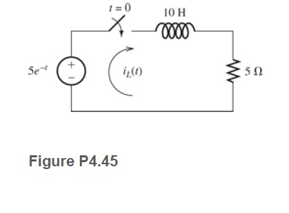

Transcribed Image Text:t = 0
10 H
Se
iL(1)
Figure P4.45
Expert Solution
This question has been solved!
Explore an expertly crafted, step-by-step solution for a thorough understanding of key concepts.

This is a popular solution

Trending nowThis is a popular solution!

Step by stepSolved in 3 steps with 4 images

Knowledge Booster


Learn more about
Need a deep-dive on the concept behind this application? Look no further. Learn more about this topic, electrical-engineering and related others by exploring similar questions and additional content below.Similar questions
- Consider the circuit shown in Figure P4.50. The initial current in the inductor is i s ( 0+)=0. Write the differential equation for i s(t) and solve. [Hint: Try a particular solution of the form i sp ( t )=A cos( 300t )+B sin( 300t ).]arrow_forward4.61 In the circuit shown in Figure P4.61: VS1 = 15 V Vs2 = 9 V Rs1 = 130 Q R$2 = 290 22 R₁ = 1.1 kQ2 R₂ = 700 Q L = 17 mH C = 0.35 µF Determine the voltage vc across the capacitor and the current i, through the inductor as t → ∞o. Rs1 Vsi t=0 iL LR₁ Figure P4.61 CVC R$2 с +21 ww R₂ V s2arrow_forwardGive the expression for the time constant of a circuit consisting of an inductance with an initial current in series with a resistance R. To attain a long time constant, do we need large or small values for R? For L?arrow_forward
- P4.23. Solve for the steady-state values of i1, i2, i3, i4, and vc for the circuit shown in Figure P4.23, after the switch has been closed for a long time. i iz 14 1 H 500 2 100 V 50 2 100 2 vc 100 µF Figure P4.23arrow_forwardQ4. The equation relating the current in a circuit with time is i=282.1 sin377t, where the current is measured in amperes and the time in seconds. Find the values of: The r.m.s current The frequency The instantenous value of the current when t=2.0msarrow_forwardP4.34. Consider the circuit shown in Figure P4.34. The initial current in the inductor is iL (0-) 0. Find expressions for i (t) and v(t) for t> 0 and sketch to scale versus time. 0.1 A (1) R = v(t) 1 k2 t = 0 1 mH Figure P4.34arrow_forward
- A controlled rectifier circuit is generating thewaveform of Figure P4.30 starting from a sinusoidalvoltage of 110 V rms. Find the average and rmsvoltage.arrow_forwardIn the circuit shown in Figure P4.7, let for - 00arrow_forwardQuestion 4. In the circuit below I is a DC current, and v. is a sinusoidal signal. Given the diode has vo-0.75V at ip=1.5mA, calculate both the AC and DC voltage across the diode (v.) when I=1mA, R=5002, and Vs=100cos(10*n*t). Assume the capacitors are very large. R₂ www -0 ▷ +1₁ 15 B ANarrow_forward
- P4.17. Consider the circuit of Figure P4.17, in which the switch instantaneously moves back and forth between contacts A and B, spending 2 seconds in each position. Thus, the capacitor repeatedly charges for 2 seconds and then discharges for 2 seconds. Assume that v C ( 0 )=0 and that the switch moves to position A at t=0. Determine V C ( 2 ), v C ( 4 ), vC(6 ), and v C ( 8). I MO 10 Varrow_forwardDetermine expressions for and sketch is(t) toscale versus time for -0.2 … t … 1.0 s for thecircuit of Figure P4.37 using a differential equation.arrow_forward4.65 The switch shown in Figure P4.65 is thrown at f = 0. Assume a DC steady-state for t 0. R₂ 1=0 V₂ Figure P4.65 mw L R₁ V₂ = 12 V R, = 31 ΚΩ L = 0.9 mH C R₂ = 100 £2 R₂-22 k2 C=0.5 μF R₂arrow_forward
arrow_back_ios
SEE MORE QUESTIONS
arrow_forward_ios
Recommended textbooks for you
- Introductory Circuit Analysis (13th Edition)Electrical EngineeringISBN:9780133923605Author:Robert L. BoylestadPublisher:PEARSON
 Delmar's Standard Textbook Of ElectricityElectrical EngineeringISBN:9781337900348Author:Stephen L. HermanPublisher:Cengage Learning
 Programmable Logic ControllersElectrical EngineeringISBN:9780073373843Author:Frank D. PetruzellaPublisher:McGraw-Hill Education
  Fundamentals of Electric CircuitsElectrical EngineeringISBN:9780078028229Author:Charles K Alexander, Matthew SadikuPublisher:McGraw-Hill Education
 Electric Circuits. (11th Edition)Electrical EngineeringISBN:9780134746968Author:James W. Nilsson, Susan RiedelPublisher:PEARSON
 Engineering ElectromagneticsElectrical EngineeringISBN:9780078028151Author:Hayt, William H. (william Hart), Jr, BUCK, John A.Publisher:Mcgraw-hill Education,
Introductory Circuit Analysis (13th Edition)
Electrical Engineering
ISBN:9780133923605
Author:Robert L. Boylestad
Publisher:PEARSON
Delmar's Standard Textbook Of Electricity
Electrical Engineering
ISBN:9781337900348
Author:Stephen L. Herman
Publisher:Cengage Learning
Programmable Logic Controllers
Electrical Engineering
ISBN:9780073373843
Author:Frank D. Petruzella
Publisher:McGraw-Hill Education
Fundamentals of Electric Circuits
Electrical Engineering
ISBN:9780078028229
Author:Charles K Alexander, Matthew Sadiku
Publisher:McGraw-Hill Education
Electric Circuits. (11th Edition)
Electrical Engineering
ISBN:9780134746968
Author:James W. Nilsson, Susan Riedel
Publisher:PEARSON
Engineering Electromagnetics
Electrical Engineering
ISBN:9780078028151
Author:Hayt, William H. (william Hart), Jr, BUCK, John A.
Publisher:Mcgraw-hill Education,