
Videos
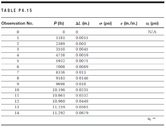
A tension test was performed on an aluminum alloy specimen to fracture. The original diameter of the specimen is 0.5 in. and the gauge length is 2.0 in. The information obtained from this experiment consists of applied tensile load (P) and increase in length (ΔL). The results are tabulated in Table P4.15. Using a spreadsheet program, complete the table by calculating engineering stress (σ) and engineering strain (ε). Determine the toughness of the material (ut) by calculating the area under the stress–strain curve, namely,
where εf is the strain at fracture. The preceding integral can be approximated numerically using a trapezoidal integration technique:
Want to see the full answer?
Check out a sample textbook solution
Chapter 4 Solutions
Materials for Civil and Construction Engineers (4th Edition)


- A tensile test was performed on a metal specimen having a circular cross section with a diameter of 1 2 inch. The gage length (the length over which the elongation is measured) is 2 inches. For a load 13.5 kips, the elongation was 4.6610 3 inches. If the load is assumed to be within the linear elastic rang: of the material, determine the modulus of elasticity.arrow_forwardThe data in Table 1.5.3 were obtained from a tensile test of a metal specimen with a rectangular cross section of 0.2011in.2 in area and a gage length (the length over which the elongation is measured) of 2.000 inches. The specimen was not loaded to failure. a. Generate a table of stress and strain values. b. Plot these values and draw a best-fit line to obtain a stress-strain curve. c. Determine the modulus of elasticity from the slope of the linear portion of the curve. d. Estimate the value of the proportional limit. e. Use the 0.2 offset method to determine the yield stress.arrow_forward1. The following data were obtained during a tension test of an aluminum alloy. The initial diameter of the test specimen was 0.505 in., and the gage length was 2.0 in. Load ( Ib) Elongation (in.) Load ( Ib) Elongation (in.) 14000 0.020 2310 0.0022 14400 0.025 4640 0.0044 14 500 0.060 6950 0.0066 14600 0.080 9290 0.0088 14800 0.100 I1 600 0.0110 14600 0.120 13000 0.01 50 13600 Fracture Plot the stress-strain diagram and determine the following mechanical properties: a. proportional limit þ. modulus of elasticity S. vield stress at 0.2% offset d. ultimate stress e. nominal rupture stress.arrow_forward
- The following data were obtained from the tensile test of Aluminum alloy. The initial diameter of test specimen was 0.505 inch and gauge length was 2.0 inch. Plot the stress strain diagram and determine (a) Proportional Limit (b) Modulus of Elasticity (c) Yield Stress at 0.2% offset (d) Ultimate Stress and (e) Nominal Rupture Stress. st 0.8 015 Load (Ib) Elongation (in.) Load (Ib) Elongation (in.) 14 000 0.020 2310 0.0022 14400 0.025 4640 0.0044 14 500 0.060 6950 0.0066 14 600 0.080 9 290 0.0088 14 800 0.100 11 600 13 000 0.0110 14 600 0.120 0.0150 13 600 Fracturearrow_forwardThe elastic portion of the tension stress-strain diagram for an aluminum alloy is shown in the figure. The specimen used for the test has a gauge length of 2 in. and a diameter of 0.5 in. If the applied load is 10 kip, determine the new diameter of the specimen. The shear modulus is G al =3.811032 ksiarrow_forwardAn aluminum alloy bar with a rectangular cross section that has a width of 12.5 mm, thickness of 6.25 mm, and a gauge length of 50 mm was tested in tension to fracture according to ASTM E-8 method. The load and deformation data were as shown in Table P4.6. Using a spreadsheet program, obtain the following: a. A plot of the stress-strain relationship. Label the axes and show units. b. A plot of the linear portion of the stress-strain relationship. Determine the modulus of elasticity using the best fit approach. c. Proportional limit. d. Yield stress at an offset strain of 0.002 m/m. e. Tangent modulus at a stress of 450 MPa. f. Secant modulus at a stress of 450 MPa. TABLE P4.6 Load (kN) AL (mm) Load (kN) AL (mm) 33.5 1.486 3.3 0.025 35.3 2.189 14.0 0.115 37.8 3.390 25.0 0.220 39.8 4.829 29.0 0.406 40.8 5.961 30.6 0.705 41.6 7.386 31.7 0.981 41.2 8.047 32.7 1.245arrow_forward
- A steel specimen is tested in tension. The specimen is 25 mm wide by 12.5 mm thick in the test region. By monitoring the load dial of the testing machine, it was found that the specimen yielded at a load of 160 kN and fractured at 214 kN. a. Determine the tensile stress at yield and at fracture. b. If the original gauge length was 100 mm, estimate the gauge length when the specimen is stressed to 1/2 the yield stress.arrow_forward5. A tensile test was done on a magnesium sample of original diameter and original length of 12mm 30mm respectively. The final length and diameter were 32.61mm and 11.74mm respectively. Plot the stress versus strain graph and determine: a. 0.2% proof stress b. Tensile strength c. % elongation d. % reduction e. Stress at fracture f. Modulus of Elasticity. 66 Force (N) Ext. 0.0112 0.0157 0.0199 0.0240 1.72 (mm) 177 327 462 797 1350 1720 2220 2690 2690 5.55 8.15 13.07 22.77 25.25arrow_forwardAn aluminum alloy bar with a radius of 7 mm was subjected to tension until fracture and produced results shown in Table P4 a. Using a spreadsheet program, plot the stress–strain relationship. b. Calculate the modulus of elasticity of the aluminum alloy. c. Determine the proportional limit. d. What is the maximum load if the stress in the bar is not to exceed the proportional limit? e. Determine the 0.2% offset yield strength. f. Determine the tensile strength. g. Determine the percent of elongation at failure.arrow_forward
- A high-yield-strength alloy steel bar with a rectangular cross section that has a width of 37.5 mm, a thickness of 6.25 mm, and a gauge length of 203 mm was tested in tension to rupture, according to ASTM E-8 method. The load and deformation data were as shown in Table Using a spreadsheet program, obtain the following:a. A plot of the stress–strain relationship. Label the axes and show units.b. A plot of the linear portion of the stress–strain relationship. Determine modulus of elasticity using the best-fit approach.c. Proportional limit.d. Yield stress.e. Ultimate strength.f. If the specimen is loaded to 155 kN only and then unloaded, what is the permanent deformation?g. In designing a typical structure made of this material, would you expect the stress applied in (f) safe? Why?arrow_forwardTesting a round steel alloy bar with a diameter of 15 mm and a gauge length of 250 mm produced the stress–strain relationship shown in Figure Determinea. the elastic modulusb. the proportional limitc. the yield strength at a strain offset of 0.002d. the tensile strengthe. the magnitude of the load required to produce an increase in length of 0.38 mmf. the final deformation, if the specimen is unloaded after being strained by the amount specified in (e)g. In designing a typical structure made of this material, would you expect the stress applied in (e) reasonable? Why?arrow_forwardA steel alloy specimen having a rectangular cross section of dimensions 19.1 mm x 3.1 mm (0.7520 in. × 0.1220 in.) has the stress-strain behavior shown in the Animated Figure 6.22b. If this specimen is subjected to a tensile force of 98290 N (22100 Ib;) then (a) Determine the amount of elastic strain induced. (b) Determine the amount of plastic strain induced. (c) If its original length is 610 mm, what will be its final length after this force is applied and then released? The elastic modulus for steel is 207 GPa. (a) i (b) i (c) i mmarrow_forward
 Steel Design (Activate Learning with these NEW ti...Civil EngineeringISBN:9781337094740Author:Segui, William T.Publisher:Cengage Learning
 Materials Science And Engineering PropertiesCivil EngineeringISBN:9781111988609Author:Charles GilmorePublisher:Cengage Learning