
Concept explainers
Videos
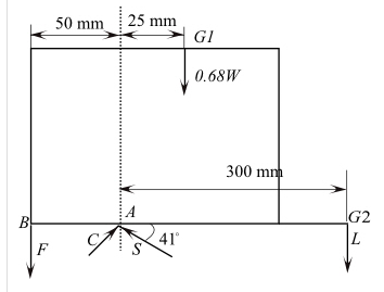
The lumbar portion of the human spine supports the entire weight of the upper torso and the force load imposed on it. We consider here the disk (shaded red) between the lowest vertebra of the lumbar region
Want to see the full answer?
Check out a sample textbook solution
Chapter 3 Solutions
Engineering Mechanics: Statics


- The wheels, axle, and handles of a wheelbarrow W=62N. The load chamber and its contents weigh Wl=575N. The drawing chose leave to Forsyth and different wheelbarrow designs to support the wheelbarrow and equilibrium the man's hands apply a force to the handles that is directly vertically upward. consider the rotational axis at the point where the tire contacts the ground, directed perpendicular to the plane of the paper. Find the magnitude of the Man's force for both designsarrow_forwardThe figure shows the Russel fracture traction device and a mechanical model of the leg. The leg is held in balance in the position indicated by the two weights attached to the two cables. The combined weight of the leg and cast is W=180 N. The horizontal distance between points A and B where the cables are attached to the leg is L=100 cm and the vertical distance is d=5 cm. Point C is the center of gravity of the cast and leg at three quarters of the L measured from point A (3L/4= 75 cm). The angle that cable 2 makes with the horizontal is measured as β=30°. Accordingly, in order for the leg to remain in balance in the shown position; a) Find the tensile force T1 in cable 1. (Write your result in N) Answerb) Find the tensile force T2 in cable 2. (Write your result in N) Answerc) Find the angle α of cable 1 with the horizontal. Responsearrow_forwardThe figure shows a mechanical model of the Russel fracture traction device and the leg. The leg is held in balance in the position indicated by the two weights attached to the two cables. The total weight of the leg and the cast is W=200 N. The horizontal distance between points A and B where the cables are attached to the leg is L=100 cm and the vertical distance is d=10 cm . Point C is the center of gravity of the cast and leg at three quarters of the L measured from point A ( 3L/4= 75 cm) . The angle that cable 2 makes with the horizontal is measured as β=40 ° . Accordingly, in order for the leg to remain in balance in the position shown; a) Find the tensile force T 1 in cable 1 . (Write your result in N ) b) Find the tensile force T 2 in cable 2 . (Write your result in N ) c) Find the angle α of cable 1 with the horizontalarrow_forward
- For the spring assemblage shown below, determine the displacement at node 2 and the forces in each spring element. Also determine the force F3. Given: Node 3 displaces an amount 8 = 12.5 mm in the positive x direction because of the force F3 and k1 k2 175 kN/m.arrow_forwardThe structure consists of a spring CD and a solid member ABC with a slot at B. The peg at B fits loosely into the slot at B and can hence be interpreted as a smooth support. The unstretched length of the spring is 80 mm. 50 mm 150 mm 50 mm A D C B k = 600 N/m 1.1 Draw separate free-body diagrams of member ABC and the spring CD. 1.2 Comment on the existence of two-force members and three-force members in this system. 1.3 Determine the reactions at A and B on the member ABCarrow_forwardThe arm in the figure below weighs 37.6 N. The force of gravity acting on the arm acts through point A. Determine the magnitudes of the tension force F, in the deltoid muscle and the force i, exerted by the shoulder on the humerus (upper-arm bone) to hold the arm in the position shown. (Enter your answers to at least the nearest newton.) N %3D 0.080 m 0.290 m-arrow_forward
- The arm in the figure below weighs 41.6 N. The force of gravity acting on the arm acts through point A. Determine the magnitudes of the tension force Ft in the deltoid muscle and the force Fs exerted by the shoulder on the humerus (upper-arm bone) to hold the arm in the position shown. F 0.080 m -0.290 m TE brarrow_forwardFigure 1 shows a simple system to lift a heavy load. The dimensions a = 3.6 m and b = 1.2 m. The mass of the bar and counterweight is 45000 g, and their weight W acts at the point as shown. The mass of the load being lifted is 20000g (a) (b) If the load is just above the ground, determine the vertical force the person must exert to support the system. If the load is 1 m above the ground, determine the vertical force the person must exert to support the system. 25° Figure 1 20000 g Warrow_forwardAs shown, an L-shaped bar is supported by a pin at joint A. The bar's dimensions are aaa = 620 mmmm and bbb = 400 mmmm , and the bar is subjected to a force with magnitude FFF = 5.05 kNkN at joint B. Ignoring the bar's weight, find the actual orientation of the applied force. What is the value of the angle θθtheta?arrow_forward
- The figure shows the finishing position of a body builder's arm who is performing a standing lateral raise with a 5.00-kg dumbbell. This is an excellent exercise that isolates the lateral deltoid muscle. The weight of the arm itself is 42.5 N, and it acts at point A in the figure. Given the information shown, and the fact that 0 = 9.74°, (a) find the magnitude of the tension force in the deltoid (F₁) and (b) the normal force from the shoulder joint (F acting on the humerus bone that holds the arm in this equilibrium position. S (a) Number (b) Number i Fa 0.075 m O 12⁰ 0.250 m Units Units W arm 0.510 m 5 kg WAarrow_forwardSome idiot created the three-legged table shown. X = 0 X = l W Which of the which of the legs supports about half of the table's weight? O The far leg O The left leg None. Each supports close to one-third of the table's weight. O The right leg None. Each supports approximately the entire tabe's weight.arrow_forwardA uniform beam of length 20 m and mass 100 kg is supported by pylons on either end. A 200-kg box is centered at 14 m from the right end of the beam. What is the downward force on the left most pylon? Your Answer: Answerarrow_forward
 Elements Of ElectromagneticsMechanical EngineeringISBN:9780190698614Author:Sadiku, Matthew N. O.Publisher:Oxford University Press
 Mechanics of Materials (10th Edition)Mechanical EngineeringISBN:9780134319650Author:Russell C. HibbelerPublisher:PEARSON
 Thermodynamics: An Engineering ApproachMechanical EngineeringISBN:9781259822674Author:Yunus A. Cengel Dr., Michael A. BolesPublisher:McGraw-Hill Education
 Control Systems EngineeringMechanical EngineeringISBN:9781118170519Author:Norman S. NisePublisher:WILEY
 Mechanics of Materials (MindTap Course List)Mechanical EngineeringISBN:9781337093347Author:Barry J. Goodno, James M. GerePublisher:Cengage Learning
 Engineering Mechanics: StaticsMechanical EngineeringISBN:9781118807330Author:James L. Meriam, L. G. Kraige, J. N. BoltonPublisher:WILEY