
Concept explainers
Videos
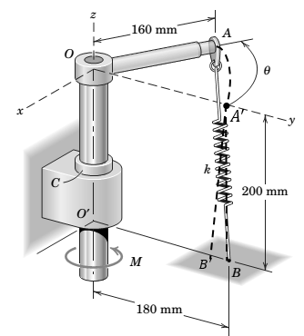
Determine and plot the moment M required to rotate arm OA over the range
Want to see the full answer?
Check out a sample textbook solution
Chapter 3 Solutions
Engineering Mechanics: Statics
Additional Engineering Textbook Solutions
Thinking Like an Engineer: An Active Learning Approach (4th Edition)
Engineering Mechanics: Statics & Dynamics (14th Edition)
Fundamentals Of Thermodynamics
Mechanics of Materials (10th Edition)
Automotive Technology: Principles, Diagnosis, And Service (6th Edition) (halderman Automotive Series)
Fox and McDonald's Introduction to Fluid Mechanics


- The member is supported by a square rod which fits loosely through the smooth square hole of the attached collar at A and by a roller at B. The member is subjected to the forces F1 = 200 N , F2 = 350 N , and F3 = 500 N . Determine the normal reaction force of roller at B. Determine the components of the reaction force of the support at A using scalar notation. Determine the components of moment of the reaction at A using scalar notation.arrow_forwardOne of the ends of the rigid rod AB of mass m and length L = 4R is attached to the edge of the radius R disc by a pin. The other end of the rod can slide freely on the ground without friction. A motor connected to the center of the disk at point O rotates the disk at a constant angular velocity D. Find all the forces acting on the rod at the moment θ = 30 degrees and the direction OB is vertical at the moment shown in the figure.arrow_forwardThe device shown is a part of an automobile seat-back-release mechanism. The part is subjected to the 3.9-N force exerted at A and a 270-N-mm restoring moment exerted by a hidden torsional spring. Determine the y-intercept of the line of action of the single equivalent force. Your answer will be positive if the intercept is above O and negative if below O.arrow_forward
- 3/61 A force of magnitude P = 180 N is applied to the stationary machine handle as shown. Write the force and moment reactions at 0 as vectors. Neglect the weight of the handle assembly. A 15 125 mm 200 mm Problem 3/61arrow_forwardCalculate the moment MO of the 190-N force about the base point O of the robot. The moment is positive if counterclockwise, negative if clockwise.Assume F = 190 N, a = 600 mm, b = 420 mm, c = 230 mm, θ= 56°, and ϕ= 30°.arrow_forwardThe throttle-control lever OA rotates in the range 0 ≤ 0≤ 90°. An internal torsional return spring exerts a restoring moment about O given by M = K(0+1/4), where K = 490 N-mm/rad and is in radians. Determine and plot as a function of the tension Trequired to make the net moment about Ozero. The effects of the radius of the pulley at Bare negligible. After you have completed the plot. answer the questions. Assumer = 65 mm, d = 145 mm. B 45° Answers: If 8 = 25%, the tension T = i If 8 = 48%, the tension T= i If 8 = 60%, the tension T = 1 N N Narrow_forward
- The member is supported by a square rod which fits loosely through the smooth square hole of the attached collar at AA and by a roller at B. The member is subjected to the forces F1 = 350 N , F2 = 450 N , and F3 = 600 N . Determine the normal reaction force of roller at B. Determine the components of the reaction force of the support at A using scalar notation. Determine the components of moment of the reaction at A using scalar notation.arrow_forwardIn a three-joint robot, L1=350mm, L2=250mm and L3=50mm. If x=300mm and Z=400mm and α=30° in two-dimensional space of the gripper, θ1, θ2Find the values of and θ3.arrow_forwardIf the 15 kg bar has a center of mass at G, calculate the resulting moment at point O.arrow_forward
- The top viewv of a revolving entrance door is shown. 0.8 m Two persons simultancously approach the door and exert forces of equal magnitudes as shown. If the resulting moment about the door pivot axis at a is 25 N .m, determine the force magnitude F from the following answers which of them is correct: 0.8 m 15° O M= 16.18 N.m O M= 0 N.m O M= 18.16 N.m M = 181.16 N.m O M= 161.8 N.marrow_forwardDetermine the moment Moz produced by the force F = -8i + 25j + 4k N which tends to rotate the rod about the z axis.arrow_forwardin the pulley system and the diagram above, assume that the bearings at oh and C are properly aligned and smooth and that T2 =30 N all dimensions in millimeters and the belt tensions are all tangential to the pulleys a. If the shaft runs at a constant speed, determine the tension T1 b draw a free body diagram of the shaft and determine the reactions at bearing sea in terms of the components along the Y and Z axis. Assume neither bearing and oh or see produces an axial thrustarrow_forward
 International Edition---engineering Mechanics: St...Mechanical EngineeringISBN:9781305501607Author:Andrew Pytel And Jaan KiusalaasPublisher:CENGAGE L