
Engineering Mechanics: Statics
8th Edition
ISBN: 9781118807330
Author: James L. Meriam, L. G. Kraige, J. N. Bolton
Publisher: WILEY
expand_more
expand_more
format_list_bulleted
Concept explainers
Videos
Textbook Question
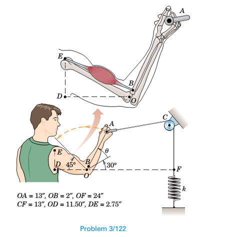
Chapter 3.5, Problem 122P
All the conditions of Prob. 3/121 are repeated here, except the weight W is replaced by a spring of constant
Expert Solution & Answer
Want to see the full answer?
Check out a sample textbook solution
Students have asked these similar questions
The weight of the limb is W=15 lbs.The contact of foot with the ground can be modeled as a pin/hinge here. Determine the reaction force of the ground and the reaction at the knee joint and its direction/angle θ. Note: use the thee force member condition to find the angle of FK.Q4.As it’s been shown in the below figure,a person is using an exercise machine. Points A and B correspond to the shoulder and elbow joints, respectively. Relative to the person, the upper arm (AB) is extended toward the left (x-direction) and the lower arm (BC) is extended forward (z-direction). At this instant, the person is holding a handle that is connected by a cable to a suspending weight. The weight applies an upward (in the y-direction) force with magnitude F on the arm at point C. The lengths of the upper arm and lower arm are AB̅̅̅̅= 20cm and BC̅̅̅̅= 25cm, respectively, and the magnitude of the applied force is F = 400 N.Determine the components of reaction developed at the shoulder joint A When the…
A 415 kg safe is hanging from the apparatus below. Determine the tension in the cable. Dimension a=1.9 m and dimension b=2.5 m. The mass of the beam is 85 kg. Use g = 10 N/kg. Hint: Take torques about the hinge and use the perpendicular lever arm version of the torque equation (the sin theta version will work but will require more calculation).
Q3 - The uniform bar OC of length L and mass ( m ) pivots freely about a horizontal axis
through O. If the spring of modulus k is unstretched when C is coincident with A, determine the
tension T required to hold the bar in the position shown. The diameter of the small pulley at D
is negligible.
T
L/2
45°
30°
B
L/2
mg
A
www
Chapter 3 Solutions
Engineering Mechanics: Statics
Ch. 3.3 - In the side view of a 50-lb flat-screen television...Ch. 3.3 - The mass center G of the 1400-kg rear-engine car...Ch. 3.3 - A carpenter carries a 12-lb 2-in. by 4-in. board...Ch. 3.3 - The 450-kg uniform I-beam supports the load shown....Ch. 3.3 - Determine the force P required to maintain the...Ch. 3.3 - The 20-kg homogeneous smooth sphere rests on the...Ch. 3.3 - The 600-lb drum is being hoisted by the lifting...Ch. 3.3 - If the screw B of the wood clamp is tightened so...Ch. 3.3 - Determine the reactions at A and E if P=500 N....Ch. 3.3 - What horizontal force P must a worker exert on the...
Ch. 3.3 - The 20-kg uniform rectangular plate is supported...Ch. 3.3 - The 500-kg uniform beam is subjected to the three...Ch. 3.3 - A former student of mechanics wishes to weigh...Ch. 3.3 - The uniform rectangular body of mass m is placed...Ch. 3.3 - What weight WB will cause the system to be in...Ch. 3.3 - The pair of hooks is designed for the hanging of...Ch. 3.3 - The winch takes in cable at the constant rate of...Ch. 3.3 - To accommodate the rise and fall of the tide, a...Ch. 3.3 - When the 0.05-kg body is in the position shown,...Ch. 3.3 - When the 0.05-kg body is in the position shown,...Ch. 3.3 - When on level ground, the car is placed on four...Ch. 3.3 - Determine the magnitude P of the force required to...Ch. 3.3 - The 180-lb exerciser is beginning to execute some...Ch. 3.3 - Three cables are joined at the junction ring C...Ch. 3.3 - Determine the moment M which the motor must exert...Ch. 3.3 - A bicyclist applies a 40-N force to the brake...Ch. 3.3 - Find the angle of tilt with the horizontal so...Ch. 3.3 - The rack has a mass m=75kg. What moment M must be...Ch. 3.3 - The elements of a wheel-height adjuster for a lawn...Ch. 3.3 - The right-angle uniform slender bar AOB has mass...Ch. 3.3 - Determine the minimum cylinder mass m1 required to...Ch. 3.3 - Cable AB passes over the small ideal pulley C...Ch. 3.3 - A pipe P is being bent by the pipe bender as...Ch. 3.3 - The small slider A is moved along the circular...Ch. 3.3 - The asymmetric simple truss is loaded as shown....Ch. 3.3 - The tailgate OBC is attached to the rear of a...Ch. 3.3 - The indicated location of the center of gravity of...Ch. 3.3 - A uniform ring of mass m and radius r carries an...Ch. 3.3 - Determine the force T required to hold the uniform...Ch. 3.3 - A block placed under the head of the claw hammer...Ch. 3.3 - The uniform slender bar of length 2r and mass m...Ch. 3.3 - The chain binder is used to secure loads of logs,...Ch. 3.3 - In a procedure to evaluate the strength of the...Ch. 3.3 - A woman is holding a 3.6-kg sphere in her hand...Ch. 3.3 - A person is performing slow arm curls with a 10-kg...Ch. 3.3 - The exercise machine is designed with a...Ch. 3.3 - For a given value m1 for the cart mass, determine...Ch. 3.3 - The device shown is used to test automobile-engine...Ch. 3.3 - The portable floor crane in the automotive shop is...Ch. 3.3 - The torsional spring of constant kT=50Nm/rad is...Ch. 3.3 - A torque (moment) of 24Nm is required to turn the...Ch. 3.3 - During an engine test on the ground, a propeller...Ch. 3.3 - To test the deflection of the uniform 200-lb beam...Ch. 3.3 - The pin A, which connects the 200-kg steel beam...Ch. 3.3 - A portion of the shifter mechanism for a manual...Ch. 3.3 - The cargo door for an airplane of circular...Ch. 3.3 - It is desired that a person be able to begin...Ch. 3.3 - Certain elements of an in-refrigerator ice-cube...Ch. 3.3 - The lumbar portion of the human spine supports the...Ch. 3.3 - Determine and plot the moment M which much be...Ch. 3.4 - A uniform steel plate 18 in. square weighing 68 lb...Ch. 3.4 - The uniform I-beam has a mass of 60 kg per meter...Ch. 3.4 - Determine the tensions in cables AB, AC, and AD.Ch. 3.4 - An 80-lb sheet of plywood rests on two small...Ch. 3.4 - The vertical and horizontal poles at the...Ch. 3.4 - The body is constructed of uniform slender rod...Ch. 3.4 - In order to make an adjustment, engineering...Ch. 3.4 - The rectangular solid is loaded by a force which...Ch. 3.4 - When on level ground, the car is placed on four...Ch. 3.4 - The uniform rectangular plate of mass m is...Ch. 3.4 - A uniform right-circular cylinder of mass m is...Ch. 3.4 - The uniform square plate is suspended by three...Ch. 3.4 - A three-legged stool is subjected to the load L as...Ch. 3.4 - The uniform slender rod of mass m is suspended by...Ch. 3.4 - One of the vertical walls supporting end B of the...Ch. 3.4 - The light right-angle boom which supports the...Ch. 3.4 - The mass center of the 30-kg door is in the center...Ch. 3.4 - The two I-beams are welded together and are...Ch. 3.4 - The 50-kg uniform triangular plate is supported by...Ch. 3.4 - The large bracket is constructed of heavy plate...Ch. 3.4 - The 800-lb tree trunk is known to have insect...Ch. 3.4 - The smooth homogeneous sphere rests in the 120...Ch. 3.4 - Determine the magnitudes of the force R and couple...Ch. 3.4 - The 25-kg rectangular access door is held in the...Ch. 3.4 - As part of a check on its design, a lower A-arm...Ch. 3.4 - The shaft, lever, and handle are welded together...Ch. 3.4 - During a test, the left engine of the twin-engine...Ch. 3.4 - The bent rod ACDB is supported by a sleeve at A...Ch. 3.4 - Turnbuckle T1 is tightened to a tension of 750 N...Ch. 3.4 - The spring of modulus k=900N/m is stretched a...Ch. 3.4 - A homogeneous door of mass m, height h, and width...Ch. 3.4 - Consider the rudder assembly of a radio-controlled...Ch. 3.4 - The upper ends of the vertical coil springs in the...Ch. 3.4 - The uniform 30- by 40-in. trap door weighs 200 lb...Ch. 3.4 - A uniform bar of length b and mass m is suspended...Ch. 3.4 - A rectangular sign over a store has a mass of 100...Ch. 3.4 - The uniform rectangular panel ABCD has a mass of...Ch. 3.4 - Determine and plot the moment M required to rotate...Ch. 3.5 - The rack for storing automobile wheels consists of...Ch. 3.5 - The positioning device locks the sliding panel C...Ch. 3.5 - The light bracket ABC is freely hinged at A and is...Ch. 3.5 - The uniform bar with end rollers weighs 60 lb and...Ch. 3.5 - The mass of the uniform right-triangular tabletop...Ch. 3.5 - The device shown in the figure is useful for...Ch. 3.5 - Magnetic tape under a tension of 10 N at D passes...Ch. 3.5 - The tool shown is used for straightening twisted...Ch. 3.5 - A freeway sign measuring 12 ft by 6 ft is...Ch. 3.5 - A slender rod of mass m1 is welded to the...Ch. 3.5 - The curved arm BC and attached cables AB and AC...Ch. 3.5 - The device shown in section can support the load L...Ch. 3.5 - A large symmetrical drum for drying sand is...Ch. 3.5 - Determine the force P required to begin rolling...Ch. 3.5 - The small tripod like stepladder is useful for...Ch. 3.5 - Each of the three uniform 1200-mm bars has a mass...Ch. 3.5 - The uniform 15-kg plate is welded to the vertical...Ch. 3.5 - A vertical force P on the foot pedal of the bell...Ch. 3.5 - The drum and shaft are welded together and have a...Ch. 3.5 - Determine and plot the tension ratio Timg required...Ch. 3.5 - Two traffic signals are attached to the 36-ft...Ch. 3.5 - The two traffic signals of Prob. 3/119 are now...Ch. 3.5 - In executing the biceps-curl exercise, the man...Ch. 3.5 - All the conditions of Prob. 3/121 are repeated...Ch. 3.5 - The basic features of a small backhoe are shown in...Ch. 3.5 - The mass center of the 1.5-kg link OC is located...Ch. 3.5 - The system of Prob. 3/60 is repeated here, but now...Ch. 3.5 - The 125-kg homogeneous rectangular solid is held...
Knowledge Booster


Learn more about
Need a deep-dive on the concept behind this application? Look no further. Learn more about this topic, mechanical-engineering and related others by exploring similar questions and additional content below.Similar questions
- A rear suspension system for a front wheel-drive vehicle is shown here. Spring EF is offset behind member CD. The normal force due to contact between the wheel and the road is 4200 N. Assume the weight of the wheel and suspension system components is negligible. Determine the magnitude of the member CD. Is the member in tension or compression? Determine the support reactions at A. Determine the unstretched length of the spring EF given a spring constant of 150 kN/m.arrow_forwardin the pulley system and the diagram above, assume that the bearings at oh and C are properly aligned and smooth and that T2 =30 N all dimensions in millimeters and the belt tensions are all tangential to the pulleys a. If the shaft runs at a constant speed, determine the tension T1 b draw a free body diagram of the shaft and determine the reactions at bearing sea in terms of the components along the Y and Z axis. Assume neither bearing and oh or see produces an axial thrustarrow_forwardQuestion 2: The ideal spring of constant k-2.6 kN/m is attached to the disk at point A and the end fitting at point B, as shown. The spring is unstretched when OA and Oв are both zero. If the disk is rotated 15° clockwise and the end fitting is rotated 30°counterclockwise, determine the vector expression for the spring force F. ( Determine distance C so that the moment the spring force makes about the Z axis is equal to 10.82 N.m. ( A = 15°. C A 250 mm eeeeeee 900 mm k= 2.6 kN/m OB = 30° B LC 7-y 200 mmarrow_forward
- Q3 - The uniform bar OC of length L and mass (m ) pivots freely about a horizontal axis through O. If the spring of modulus k is unstretched when C is coincident with A, determine the tension T required to hold the bar in the position shown. The diameter of the small pulley at D| is negligible. T D L/2 45° B 30 L/2 mg А wwwwarrow_forwardThe member is supported by a pin at A and cable BC. Suppose that r = 3.5 m and the cylinder has a mass of 40 kg . Determine the tension in the cable BC. Determine the components of reaction force at the support A using scalar notation. Determine the components of moment of reaction at the support A.arrow_forwardThe rod is supported by a ball-and-socket joint A and cables BD and CD. Suppose that www = 600 N/m . Determine the components of reaction at the ball-and-socket joint A using scalar notation. Determine the tension in the supporting cable DB. Determine the tension in the supporting cable DCDC.arrow_forward
- Masses M1 and M2 are held on the frictionless inclined plane by a rigid inextensible bar of length l as shown in diagram find the angle θ under equilibrium condition in terms of M1, M2 and θ1arrow_forwardThe following system is in static equilibrium with the strings AB, BC, and CD connected to support the 40N and 50N weights as shown. The middle string BC is exactly horizontal, and points A and D are connected to a rigid support. Calculate the tension forces T₁, T₂, T3, and the angle 8. T₁ A 35° T₁ 35⁰ B 40 N 40 N T2 T2 0 T₂ C 50 N 50 N D T3 T3arrow_forward2. Find the horizontal force P to start the motion of any part of the system of three blocks resting upon one another as shown. The weight of the blocks are W-300 KN, Ws= 100 KN and Wc =200 KN. Between A and B μ=0.30, between C and B, μ =0.20 and between C and the ground, p=0.10. 1 sni brod nog 02.0-4 B C 05.0-4 Solution: tamos quoy worla bre sosia asquar 005 300 en of jells400 N₁-300 F3 N-300- N₂=300 Assuming B and C will not move. F₁ = 300 (0.30) F₁ = 90 kN ne à bns A zelboß 1 P = 90 kN es ensla berb hebnu 02.0- y elin 05.0= q V in Celpris orllanimetsa MX 008 Assuming C will not move: al 1st F2=400 (0.20) = 80 kN OTE Bm ribirte F₂ vica Assuming the three blocks move: F3 = 0.10 (600) F3 = 60 kN P=60 KN Least force is 60 kN.arrow_forward
- Q1-Consider the below hip joint prosthesis. When standing symmetrically on both feet, a joint reaction force of F =350N is acting at the femoral head (point A) due to the body weight of the patient. The geometric parameters of the prosthesis are l1= 30 mm, l2= 40 mm, θ1= 35°, θ2= 100°. Determine the moments generated by force F about points C on the prosthesis when force F applies along line AB.arrow_forwardA person is performing slow arm curls with a 10- kg weight as indicated in the figure below. The brachialis muscle group (consisting of the bicepts and brachialis muscles) is the major factor in this exercise. Determine the magnitude F of the brachialis-muscle-group force and the magnitude E of the elbow joint reaction at point E for the forearm position shown in the figure. Use the dimensions provided to locate the effective points of application of the two muscle groups; these points are 200 mm directly above E and 50 mm directly to the right of E. Include the effect of the 1.5- kg forearm mass with mass center at point G. State any assumptions. Humerus Biceps Brachialis 200 mm Ulna 10 kg Radius E 50 mm 100 mm 350 mmarrow_forwardThe figure shows the finishing position of a body builder's arm who is performing a standing lateral raise with a 5.00-kg dumbbell. This is an excellent exercise that isolates the lateral deltoid muscle. The weight of the arm itself is 42.5 N, and it acts at point A in the figure. Given the information shown, and the fact that 0 = 9.74°, (a) find the magnitude of the tension force in the deltoid (F₁) and (b) the normal force from the shoulder joint (F acting on the humerus bone that holds the arm in this equilibrium position. S (a) Number (b) Number i Fa 0.075 m O 12⁰ 0.250 m Units Units W arm 0.510 m 5 kg WAarrow_forward
arrow_back_ios
SEE MORE QUESTIONS
arrow_forward_ios
Recommended textbooks for you
 Elements Of ElectromagneticsMechanical EngineeringISBN:9780190698614Author:Sadiku, Matthew N. O.Publisher:Oxford University Press
 Mechanics of Materials (10th Edition)Mechanical EngineeringISBN:9780134319650Author:Russell C. HibbelerPublisher:PEARSON
 Thermodynamics: An Engineering ApproachMechanical EngineeringISBN:9781259822674Author:Yunus A. Cengel Dr., Michael A. BolesPublisher:McGraw-Hill Education
 Control Systems EngineeringMechanical EngineeringISBN:9781118170519Author:Norman S. NisePublisher:WILEY
 Mechanics of Materials (MindTap Course List)Mechanical EngineeringISBN:9781337093347Author:Barry J. Goodno, James M. GerePublisher:Cengage Learning
 Engineering Mechanics: StaticsMechanical EngineeringISBN:9781118807330Author:James L. Meriam, L. G. Kraige, J. N. BoltonPublisher:WILEY
Elements Of Electromagnetics
Mechanical Engineering
ISBN:9780190698614
Author:Sadiku, Matthew N. O.
Publisher:Oxford University Press
Mechanics of Materials (10th Edition)
Mechanical Engineering
ISBN:9780134319650
Author:Russell C. Hibbeler
Publisher:PEARSON
Thermodynamics: An Engineering Approach
Mechanical Engineering
ISBN:9781259822674
Author:Yunus A. Cengel Dr., Michael A. Boles
Publisher:McGraw-Hill Education
Control Systems Engineering
Mechanical Engineering
ISBN:9781118170519
Author:Norman S. Nise
Publisher:WILEY
Mechanics of Materials (MindTap Course List)
Mechanical Engineering
ISBN:9781337093347
Author:Barry J. Goodno, James M. Gere
Publisher:Cengage Learning
Engineering Mechanics: Statics
Mechanical Engineering
ISBN:9781118807330
Author:James L. Meriam, L. G. Kraige, J. N. Bolton
Publisher:WILEY
Introduction To Engg Mechanics - Newton's Laws of motion - Kinetics - Kinematics; Author: EzEd Channel;https://www.youtube.com/watch?v=ksmsp9OzAsI;License: Standard YouTube License, CC-BY