
Engineering Mechanics: Statics
8th Edition
ISBN: 9781118807330
Author: James L. Meriam, L. G. Kraige, J. N. Bolton
Publisher: WILEY
expand_more
expand_more
format_list_bulleted
Videos
Textbook Question
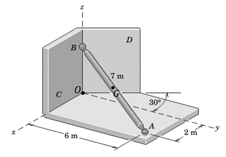
Chapter 3.4, Problem 75P
One of the vertical walls supporting end B of the 200-kg uniform shaft of Sample Problem 3/5 is turned through a 300 angle as shown here. End A is still supported by the ball-and-socket connection in the horizontal x-y plane. Calculate the magnitudes of the forces P and R exerted on the ball end B of the shaft by the vertical walls C and D, respectively.
Expert Solution & Answer
Want to see the full answer?
Check out a sample textbook solution
Students have asked these similar questions
One of the smooth vertical walls supporting
end B of the 100-kg uniform shaft is turned
through a 40° angle as shown here. End A is
supported by the ball-and-socket connection in
the horizontal x-y plane. Calculate the
magnitudes of the forces P and R exerted on the
ball end B of the shaft by the vertical walls C
and D, respectively.
Assume a = 5.6 m, b = 1.8 m, L = 6.9 m, and 0 =
40°.
A
Answers:
One of the smooth vertical walls supporting end B of the 130-kg uniform shaft is turned through a 35° angle as shown here. End A is
supported by the ball-and-socket connection in the horizontal x-y plane. Calculate the magnitudes of the forces Pand R exerted on
the ball end B of the shaft by the vertical walls Cand D, respectively.
Assume a = 5.1 m, b = 1.6 m, L = 6 m, and 0 = 35°.
D
B
Answers:
P =
i
R=
(a) Revisit the problem and solve for the cable forces TAD, TAC, and reaction force components 0,
Oy, and O₂ by invoking the cross-product formulation of moment equilibrium about point A. (b) An
alternative and powerful approach involves summing moments about a line the line OD. Start with the
vector equation of moment equilibrium about point O (since it lies on OD) and project this equation
along the line OD to solve for the cable tension TAC. Do not solve for any additional reactions.
0.8 m
X
1.6m
Z
D
1.6 m
2
1.IM
D
2m
A
B
y
F = (5î - 12 k) KN
Chapter 3 Solutions
Engineering Mechanics: Statics
Ch. 3.3 - In the side view of a 50-lb flat-screen television...Ch. 3.3 - The mass center G of the 1400-kg rear-engine car...Ch. 3.3 - A carpenter carries a 12-lb 2-in. by 4-in. board...Ch. 3.3 - The 450-kg uniform I-beam supports the load shown....Ch. 3.3 - Determine the force P required to maintain the...Ch. 3.3 - The 20-kg homogeneous smooth sphere rests on the...Ch. 3.3 - The 600-lb drum is being hoisted by the lifting...Ch. 3.3 - If the screw B of the wood clamp is tightened so...Ch. 3.3 - Determine the reactions at A and E if P=500 N....Ch. 3.3 - What horizontal force P must a worker exert on the...
Ch. 3.3 - The 20-kg uniform rectangular plate is supported...Ch. 3.3 - The 500-kg uniform beam is subjected to the three...Ch. 3.3 - A former student of mechanics wishes to weigh...Ch. 3.3 - The uniform rectangular body of mass m is placed...Ch. 3.3 - What weight WB will cause the system to be in...Ch. 3.3 - The pair of hooks is designed for the hanging of...Ch. 3.3 - The winch takes in cable at the constant rate of...Ch. 3.3 - To accommodate the rise and fall of the tide, a...Ch. 3.3 - When the 0.05-kg body is in the position shown,...Ch. 3.3 - When the 0.05-kg body is in the position shown,...Ch. 3.3 - When on level ground, the car is placed on four...Ch. 3.3 - Determine the magnitude P of the force required to...Ch. 3.3 - The 180-lb exerciser is beginning to execute some...Ch. 3.3 - Three cables are joined at the junction ring C...Ch. 3.3 - Determine the moment M which the motor must exert...Ch. 3.3 - A bicyclist applies a 40-N force to the brake...Ch. 3.3 - Find the angle of tilt with the horizontal so...Ch. 3.3 - The rack has a mass m=75kg. What moment M must be...Ch. 3.3 - The elements of a wheel-height adjuster for a lawn...Ch. 3.3 - The right-angle uniform slender bar AOB has mass...Ch. 3.3 - Determine the minimum cylinder mass m1 required to...Ch. 3.3 - Cable AB passes over the small ideal pulley C...Ch. 3.3 - A pipe P is being bent by the pipe bender as...Ch. 3.3 - The small slider A is moved along the circular...Ch. 3.3 - The asymmetric simple truss is loaded as shown....Ch. 3.3 - The tailgate OBC is attached to the rear of a...Ch. 3.3 - The indicated location of the center of gravity of...Ch. 3.3 - A uniform ring of mass m and radius r carries an...Ch. 3.3 - Determine the force T required to hold the uniform...Ch. 3.3 - A block placed under the head of the claw hammer...Ch. 3.3 - The uniform slender bar of length 2r and mass m...Ch. 3.3 - The chain binder is used to secure loads of logs,...Ch. 3.3 - In a procedure to evaluate the strength of the...Ch. 3.3 - A woman is holding a 3.6-kg sphere in her hand...Ch. 3.3 - A person is performing slow arm curls with a 10-kg...Ch. 3.3 - The exercise machine is designed with a...Ch. 3.3 - For a given value m1 for the cart mass, determine...Ch. 3.3 - The device shown is used to test automobile-engine...Ch. 3.3 - The portable floor crane in the automotive shop is...Ch. 3.3 - The torsional spring of constant kT=50Nm/rad is...Ch. 3.3 - A torque (moment) of 24Nm is required to turn the...Ch. 3.3 - During an engine test on the ground, a propeller...Ch. 3.3 - To test the deflection of the uniform 200-lb beam...Ch. 3.3 - The pin A, which connects the 200-kg steel beam...Ch. 3.3 - A portion of the shifter mechanism for a manual...Ch. 3.3 - The cargo door for an airplane of circular...Ch. 3.3 - It is desired that a person be able to begin...Ch. 3.3 - Certain elements of an in-refrigerator ice-cube...Ch. 3.3 - The lumbar portion of the human spine supports the...Ch. 3.3 - Determine and plot the moment M which much be...Ch. 3.4 - A uniform steel plate 18 in. square weighing 68 lb...Ch. 3.4 - The uniform I-beam has a mass of 60 kg per meter...Ch. 3.4 - Determine the tensions in cables AB, AC, and AD.Ch. 3.4 - An 80-lb sheet of plywood rests on two small...Ch. 3.4 - The vertical and horizontal poles at the...Ch. 3.4 - The body is constructed of uniform slender rod...Ch. 3.4 - In order to make an adjustment, engineering...Ch. 3.4 - The rectangular solid is loaded by a force which...Ch. 3.4 - When on level ground, the car is placed on four...Ch. 3.4 - The uniform rectangular plate of mass m is...Ch. 3.4 - A uniform right-circular cylinder of mass m is...Ch. 3.4 - The uniform square plate is suspended by three...Ch. 3.4 - A three-legged stool is subjected to the load L as...Ch. 3.4 - The uniform slender rod of mass m is suspended by...Ch. 3.4 - One of the vertical walls supporting end B of the...Ch. 3.4 - The light right-angle boom which supports the...Ch. 3.4 - The mass center of the 30-kg door is in the center...Ch. 3.4 - The two I-beams are welded together and are...Ch. 3.4 - The 50-kg uniform triangular plate is supported by...Ch. 3.4 - The large bracket is constructed of heavy plate...Ch. 3.4 - The 800-lb tree trunk is known to have insect...Ch. 3.4 - The smooth homogeneous sphere rests in the 120...Ch. 3.4 - Determine the magnitudes of the force R and couple...Ch. 3.4 - The 25-kg rectangular access door is held in the...Ch. 3.4 - As part of a check on its design, a lower A-arm...Ch. 3.4 - The shaft, lever, and handle are welded together...Ch. 3.4 - During a test, the left engine of the twin-engine...Ch. 3.4 - The bent rod ACDB is supported by a sleeve at A...Ch. 3.4 - Turnbuckle T1 is tightened to a tension of 750 N...Ch. 3.4 - The spring of modulus k=900N/m is stretched a...Ch. 3.4 - A homogeneous door of mass m, height h, and width...Ch. 3.4 - Consider the rudder assembly of a radio-controlled...Ch. 3.4 - The upper ends of the vertical coil springs in the...Ch. 3.4 - The uniform 30- by 40-in. trap door weighs 200 lb...Ch. 3.4 - A uniform bar of length b and mass m is suspended...Ch. 3.4 - A rectangular sign over a store has a mass of 100...Ch. 3.4 - The uniform rectangular panel ABCD has a mass of...Ch. 3.4 - Determine and plot the moment M required to rotate...Ch. 3.5 - The rack for storing automobile wheels consists of...Ch. 3.5 - The positioning device locks the sliding panel C...Ch. 3.5 - The light bracket ABC is freely hinged at A and is...Ch. 3.5 - The uniform bar with end rollers weighs 60 lb and...Ch. 3.5 - The mass of the uniform right-triangular tabletop...Ch. 3.5 - The device shown in the figure is useful for...Ch. 3.5 - Magnetic tape under a tension of 10 N at D passes...Ch. 3.5 - The tool shown is used for straightening twisted...Ch. 3.5 - A freeway sign measuring 12 ft by 6 ft is...Ch. 3.5 - A slender rod of mass m1 is welded to the...Ch. 3.5 - The curved arm BC and attached cables AB and AC...Ch. 3.5 - The device shown in section can support the load L...Ch. 3.5 - A large symmetrical drum for drying sand is...Ch. 3.5 - Determine the force P required to begin rolling...Ch. 3.5 - The small tripod like stepladder is useful for...Ch. 3.5 - Each of the three uniform 1200-mm bars has a mass...Ch. 3.5 - The uniform 15-kg plate is welded to the vertical...Ch. 3.5 - A vertical force P on the foot pedal of the bell...Ch. 3.5 - The drum and shaft are welded together and have a...Ch. 3.5 - Determine and plot the tension ratio Timg required...Ch. 3.5 - Two traffic signals are attached to the 36-ft...Ch. 3.5 - The two traffic signals of Prob. 3/119 are now...Ch. 3.5 - In executing the biceps-curl exercise, the man...Ch. 3.5 - All the conditions of Prob. 3/121 are repeated...Ch. 3.5 - The basic features of a small backhoe are shown in...Ch. 3.5 - The mass center of the 1.5-kg link OC is located...Ch. 3.5 - The system of Prob. 3/60 is repeated here, but now...Ch. 3.5 - The 125-kg homogeneous rectangular solid is held...
Knowledge Booster


Learn more about
Need a deep-dive on the concept behind this application? Look no further. Learn more about this topic, mechanical-engineering and related others by exploring similar questions and additional content below.Similar questions
- The bent rod of negligible weight is supported by the ball-and-socket joint at B and the cables attached to points A and C. Find the forces in the cables and the magnitude of the reaction at B. Dimensions Figure P.5.39arrow_forwardFind the internal force system acting on section 3 for the pin-connected frame.arrow_forwardThe figure shows a wire cutter. Determine the cutting force on the wire at A when the 75-N forces are applied to the handgrips. (Hint: The horizontal components of pin forces at B and D are zero due to symmetry.)arrow_forward
- One of the smooth vertical walls supporting end B of the 230-kg uniform shaft is turned through a 21° angle as shown here. End A is supported by the ball-and-socket connection in the horizontal x-y plane. Calculate the magnitudes of the forces P and R exerted on the ball end B of the shaft by the vertical walls C and D, respectively. Assume a = 5.6 m, b = 2.3 m, L = 6.5 m, and 0 = 21° Answers: P = 2245 R = H. B a L D N A !N barrow_forward2: This fuel pump uses the reciprocating action of rocker arm ABC. The arm is pinned at B and is spring loaded at A and D. Calculate the forces acting at pin B and in the spring at point D. Fc= 125 N FA = 60 N 20 mm- 10 mm 50 mmarrow_forward3. For the one-dimensional 4 truss-element system shown, determine the nodal displacements and reaction forces using the direct stiffness method. K3=45 lb/in for F=75 lbs KI=25 lb/in K2=35 lb/in K=30 lb/inarrow_forward
- A person is performing slow arm curls with 10-kgWeight as idicated in the left image of the figure below. The biceps group (consisting of the biceps and brachialis muscles) is the major factor in this exercise. Determine the magnitude F7 of the biceps group force and the magnitude 4 of the elbow joint reaction at point E for the forearm position. The free body diagram is shown in the right image of the figure. Take the dimensions shown to locate the effectivepoints of application of the biceps group; these points are 200 mm directly above E and 50 mm directly to the right of E. Include the eftect of the the 1.5-kg forearm mass with mass center at point G. Assuming that humerus is perfectly vertical and fixed; therefore, the elbow joint E is acting like pin connection. The forearm (E-B-G-C) is perfectly horizontal; therefore, the angle A-E-B is 90 deg.arrow_forward3. The image below depicts a truss structure used to lift Mini Cooper S Roadsters. As can be seen the weight of the vehicle (2,800 lb.) is attached to the structure at joint D and directed in the negative z-direction. The coordinates for the joints (assumed to be of the ball and socket type) can be found in the table below. Determine the forces in each truss member by developing a system of linear equations and using the solve command in Sage to find the solution. - HINT: Isolate joint D and draw a free body diagram. By summing the forces in the x, y, and z directions you will obtain a linear system of three equations and three unknowns. Joint Location (0,-2,5) (0,3,5) (0,0,0) (6,0,4) OF хXarrow_forwardThe crate weighs 6.5lb and is supported by stick BC. Find the magnitude and direction of the reaction at A and the compression force in stick BC using (a) the concepts of two and three-force bodies (using close polygon method). (b) Check your answers by doing sum of the forces and moments.arrow_forward
- A uniform rigid disk has mass "M" and radius "a", and a rigid uniform rod has mass "m" and length "b". The bar is located along the vertical axis of symmetry of the disk with one end in contact with the disk. Find the force required to separate the bar from the disk. The bar is on the disk.arrow_forwardis formed in a quar- C6-67 The lever shown in Fig. ter circular arc of radius 20 in. Plot A and B, the magnitude of the pin force at A and the force on the smooth support B, as a function of e (0° s 0s 85°), the angle at which the support is located. 125 lb B A 20 in.arrow_forwardThe block system is stationary as shown in the figure. Compute the internal reaction of the horizontal cable GI.arrow_forward
arrow_back_ios
SEE MORE QUESTIONS
arrow_forward_ios
Recommended textbooks for you
 International Edition---engineering Mechanics: St...Mechanical EngineeringISBN:9781305501607Author:Andrew Pytel And Jaan KiusalaasPublisher:CENGAGE L
International Edition---engineering Mechanics: St...
Mechanical Engineering
ISBN:9781305501607
Author:Andrew Pytel And Jaan Kiusalaas
Publisher:CENGAGE L
BEARINGS BASICS and Bearing Life for Mechanical Design in 10 Minutes!; Author: Less Boring Lectures;https://www.youtube.com/watch?v=aU4CVZo3wgk;License: Standard Youtube License