
Digital Fundamentals (11th Edition)
11th Edition
ISBN: 9780132737968
Author: Thomas L. Floyd
Publisher: PEARSON
expand_more
expand_more
format_list_bulleted
Videos
Textbook Question
Chapter 3, Problem 47P
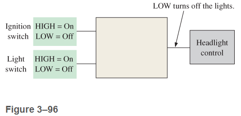
Design a circuit to fit in the beige block of Figure 3-96 that will cause the headlights of an automobile to be turned off automatically 15s after the ignition switch is turned off, if the light switch is left on. Assume that a LOW is required to turn the lights off.
Expert Solution & Answer
Want to see the full answer?
Check out a sample textbook solution
Students have asked these similar questions
1. Given ADC0804 and eight LEDS, design an ADC test circuit.
Eight LEDS are connected to eight outputs of the ADC,
respectively. The output is all 1's when the analog input is
5.1v, and all 0's when the input is Ov. Calculate and make a
table indicating analog voltage ranges which correspond to
digital number: 00H, 08H, 80H, 88H, and FFH.
4. In a series circuit with 10V applied:
A. The greater the total resistance, the less the total current
B. The greater the total current, the greater the total resistance
C. The IR voltage drops will each equal 10V
D. The sum of the IR voltage drops will equal 10V
5. When an IR voltage drop exists in a series circuit :
A. The polarity of the resistor is equal to positive
B. The polarity of the resistor is equal to negative
C. The polarity of the resistor is less than the total current on both sides
D. The polarity of the resistor is positive on one end and negative on the
other because of current flowing through it
Develop a logic circuit necessary to meet the following requirements:
A battery-powered lamp in a room is to be operated from two switches, one at the back door and one at the front door. The lamp is to be on if the front switch is on and the back switch is off, or if the front switch is off and the back switch is on. The lamp is to be off if both switches are off or if both switches are on. Let a HIGH output represent the on condition and a LOW output represent the off conditions.
The design must include the use of a chip with logic gates and the use of VHDL code.
Chapter 3 Solutions
Digital Fundamentals (11th Edition)
Ch. 3.1 - When a 1 is on the input of an inverter, what is...Ch. 3.1 - An active-HIGH pulse (HIGH level when asserted,...Ch. 3.2 - When is the output of an AND gate HIGH?Ch. 3.2 - When is the output of an AND gate LOW?Ch. 3.2 - Describe the truth table for a 5-input AND gate.Ch. 3.3 - When is the output of an OR gate HIGH?Ch. 3.3 - When is the output of an OR gate LOW?Ch. 3.3 - Describe the truth table for a 3-input OR gate.Ch. 3.4 - When is the output of a NAND gate LOW?Ch. 3.4 - When is the output of a NAND gate HIGH?
Ch. 3.4 - Describe the functional differences between a NAND...Ch. 3.4 - Write the output expression for a NAND gate with...Ch. 3.5 - When is the output of a NOR gate HIGH?Ch. 3.5 - When is the output of a NOR gate LOW?Ch. 3.5 - Describe the functional difference between a NOR...Ch. 3.5 - Write the output expression for a 3-input NOR with...Ch. 3.6 - When is the output of an XOR gate HIGH?Ch. 3.6 - When is the output of an XNOR gate HIGH?Ch. 3.6 - How can you use an XOR gate to detect when two...Ch. 3.7 - List six process technologies used for...Ch. 3.7 - What does the term volatile mean in relation to...Ch. 3.7 - What are two design entry methods for programming...Ch. 3.7 - Prob. 4CUCh. 3.7 - Write a VHDL description of a 3-input NOR gate,Ch. 3.7 - Write a VHDL description of an XOR gate.Ch. 3.8 - How is fixed-function logic different than PLD...Ch. 3.8 - Prob. 2CUCh. 3.8 - Identify the following IC logic designators: LS HC...Ch. 3.8 - Prob. 4CUCh. 3.8 - What does the term hex inverter mean? What does...Ch. 3.8 - A positive pulse is applied to an inverter input....Ch. 3.8 - A certain gate has a propagation delay time of 6...Ch. 3.8 - Prob. 8CUCh. 3.8 - Prob. 9CUCh. 3.8 - Prob. 10CUCh. 3.9 - Prob. 1CUCh. 3.9 - If two different input waveforms are applied to a...Ch. 3.9 - Prob. 3CUCh. 3 - An inverter performs the NOR operation.Ch. 3 - An AND gate can have only two inputsCh. 3 - If any input to an OR is 1, the output is 1.Ch. 3 - If all inputs to an AND gate are 1, the output is...Ch. 3 - A NAND gate has an output that is opposite the...Ch. 3 - A NOR gate can be considered as an OR gate...Ch. 3 - The output of an exclusive-OR is 0 if the inputs...Ch. 3 - Prob. 8TFQCh. 3 - Once programmed, PLD logic can be changed.Ch. 3 - Fan-out is the number of similar gates that a...Ch. 3 - When the input to an inverter is HIGH (1), the...Ch. 3 - An inverter performs an operation known as...Ch. 3 - The output of an AND gate with inputs A, B, and C...Ch. 3 - The output of an OR gate with inputs A, B, and C...Ch. 3 - A pulse is applied to each input of a 2-input NAND...Ch. 3 - A pulse is applied to each input of a 2-input NOR...Ch. 3 - A pulse is applied to each input of an...Ch. 3 - Prob. 8STCh. 3 - The purpose of a programmable link in an AND array...Ch. 3 - The term OTP means open test point one-time...Ch. 3 - Prob. 11STCh. 3 - Prob. 12STCh. 3 - Two ways to enter a logic design using PLD...Ch. 3 - Prob. 14STCh. 3 - In-system programming of a PLD typically utilizes...Ch. 3 - To measure the period of a pulse waveform, you...Ch. 3 - Prob. 17STCh. 3 - The input waveform shown in Figure 3-76 is applied...Ch. 3 - A combination of inverters is shown in Figure...Ch. 3 - If the waveform in Figure 3-76 is applied to point...Ch. 3 - Draw the rectangular outline symbol for a 4-input...Ch. 3 - Determine the output, X, for a 2-input AND gate...Ch. 3 - Repeat problem 5 for the waveforms in Figure 3-79Ch. 3 - The input wave forms applied to a 3-input AND gate...Ch. 3 - The input waveforms applied to a 4-input AND gate...Ch. 3 - Draw the rectangular outline symbol for a 3-input...Ch. 3 - Write the expression for a 5-input OR gate with...Ch. 3 - Determine the output for a 2-input OR gate when...Ch. 3 - Repeat Problem 7 for a 3-input OR gate.Ch. 3 - Repeat Problem 8 for a 4-input OR gate.Ch. 3 - For the five input waveforms in Figure 3-8219,...Ch. 3 - Draw the rectangular outline symbol for a 4-input...Ch. 3 - Show the truth table for a 3-input OR gate.Ch. 3 - For the set of input waveforms in Figure 3-83,...Ch. 3 - Determine the gate output for the input waveforms...Ch. 3 - Determine the output waveform in Figure 3-8513Ch. 3 - As you have learned, the two logic symbols shown...Ch. 3 - Repeat Problem 17 for a 2-input NOR gate.Ch. 3 - Determine the output waveform in Figure 3-87 and...Ch. 3 - Repeat Problem 19 for a 4-input NOR gate.Ch. 3 - The NAND and the negative-OR symbols represent...Ch. 3 - How does an exclusive-OR gate differ from an OR...Ch. 3 - Repeat Problem 17 for an exclusive-OR gate.Ch. 3 - Repeat Problem 17 for an exclusive-NOR gateCh. 3 - Determine the output of an exclusive-OR gate for...Ch. 3 - In the simple programmed AND array with...Ch. 3 - Determine by row and column number which fusible...Ch. 3 - Describe a 4-input AND gate using VHDL.Ch. 3 - Describe a 5-input NOR gate using VHDLCh. 3 - In the comparison of certain logic devices, it is...Ch. 3 - Prob. 34PCh. 3 - Determine tPLHandtPHL from the oscilloscope...Ch. 3 - Prob. 36PCh. 3 - If a logic gate operates on a dc supply voltage of...Ch. 3 - The variable ICCH represents the dc supply current...Ch. 3 - Examine the conditions indicated in Figure 3-92,...Ch. 3 - Determine the faulty gates in Figure 3-93 by...Ch. 3 - Using an oscilloscope, you make the observations...Ch. 3 - Prob. 42PCh. 3 - Every time the ignition switch is turned on in the...Ch. 3 - What failure(s) would you suspect if the output of...Ch. 3 - Modify the frequency counter in Figure 3-16 to...Ch. 3 - Prob. 46PCh. 3 - Design a circuit to fit in the beige block of...Ch. 3 - Modify the logic circuit for the intrusion alarm...Ch. 3 - Further modify the logic circuit from Problem 48...Ch. 3 - Sensors are used to monitor the pressure and the...Ch. 3 - In a certain automated manufacturing process,...Ch. 3 - Open file P03-52. For the specified fault, predict...Ch. 3 - Open file P03-53. For the specified fault, predict...Ch. 3 - Open file P03-54. For the observed behavior...Ch. 3 - Open file P03-55. For the observed behavior...
Additional Engineering Textbook Solutions
Find more solutions based on key concepts
3.12 (Date Create a class called Date that includes three pieces Of information as data
members—a month (type ...
C++ How to Program (10th Edition)
The Python built-in function str () will convert a numerical argument into a character string representation, a...
Computer Science: An Overview (13th Edition) (What's New in Computer Science)
A_________-controlled loop uses a true/false condition to control the number of times that it repeats. a. Boole...
Starting Out with Python (4th Edition)
Assume a program named MailList.java is stored in the DataBase folder on your hard drive. The program creates o...
Starting Out with Java: From Control Structures through Data Structures (4th Edition) (What's New in Computer Science)
How many times will the selection sort swap the smallest value in an array with another value?
Starting Out with Java: From Control Structures through Objects (7th Edition) (What's New in Computer Science)
When two operators share an operand, the operator with the highest _____ executes first.
Starting Out With Visual Basic (8th Edition)
Knowledge Booster


Learn more about
Need a deep-dive on the concept behind this application? Look no further. Learn more about this topic, computer-science and related others by exploring similar questions and additional content below.Similar questions
- The gates in the exclusive-OR circuit below have delays of 2 ns for the inverter, 5 ns for the AND gate, and 7 ns for the OR gate. The circuit's input goes from xy = 10 to xy = 11. Determine the signals at the output of each gate from t = 0 to t = 60 ns.arrow_forwardThe shift between the voltage of Phase A and B in a three phase system is O 120 degree O 0 degree O 240 degree O 60 degreearrow_forwardWith a counter 10 lights will be controlled. At the first clock pulse all lights will be ON (1). at the following pulses, lights will be off from inside to outside and the ones that are OFF will not be ON. According to which modulo must this design work ?arrow_forward
- 1. Given the following circuit: 5 ns D. 1ons The gate delays are as shown above the gates. A, B, C are three input, and all of them are varying, as given below: A = 0 at time 0, and stays constant until time = 20 ns, when it changes to 1 and stays constant there after B = 1 at time = 0, and stays at 1 value until time = 35 ns, and then changes to 0 at35 ns, and stays constant after that. !3! %3D C= 0 at time 0 and changes to 1 at 50ns Plot A, B, C upto time = 70 ns.arrow_forward3- Design the logic circuit for the following conditions and draw the output wave form : X is a 0 if any two of the three variable A,B, and C are 1X is a 1 for all other conditions ?arrow_forwardDesign a logic circuit whose output is HIGH only when a majority of inputs A, B, and C are LOW. Draw the circuit using all NAND gates.arrow_forward
- 60. Energy equation of pulse of the logic transition, can be computed as a. Energydynamic ? Capacitive load b. Energydynamic 1/? Capacitive load c. Energydynamic ? Capacitive load - Voltage2 d. Energydynamic ? Capacitive load + Voltage2arrow_forwardDesign a circuit where each time PB1 is pressed and released output Q1 turns on for 1 seconds, off for 1 seconds, on for 2 second and then stops.arrow_forwardIV. PROCEDURES: For the AND gate look on the data sheets, connect the circuit on Breadboard and test the gate. Using logic switches SW1 and SW2, apply the logic levels 0 and 1 to gate inputs Create a truth table and record the results Also simulate the given gate using the Circuit Wizard simulation software Obtain the corresponding circuit diagram using the simulation software of the Boolean expression F((A,B,C)= АВ* AC * ВС From the obtain circuit diagram develop the corresponding truth table From the figure below obtain the equivalent Boolean expression and develop its corresponding truth Table АП сПо- Boolean Expression: Z= (AB)(CD)arrow_forward
- Find the truth table of this circuit and write the function: a) NOT A OR NOT OR Y C b) NOT AND OR NOT Y OR Carrow_forwardExplain the functionality of the circuit in Fig B4 using truth table. Write a Boolean expression for X.arrow_forwardDesign a combinational circuit with four inputs, w, x, y, and z, and four outputs, A, B, C and D. When the binary input is 0, 1, 2, 3, 4,5,6 the binary output is two greater than the input. When the binary input is 7,8, 9, 10, 12,13,14,15 the binary output is three less than the input.a) Derive the Boolean expressions for four outputs A, B, C and D.. Evaluate the outputs as a function of the four inputs.(b) List the truth table with 16 binary combinations of the four input variables w, x, y, and z.(c) Draw the logic gate circuit.(d) Write Gate Level HDL code for the corresponding to the logic gate circuit.arrow_forward
arrow_back_ios
SEE MORE QUESTIONS
arrow_forward_ios
Recommended textbooks for you
 Database System ConceptsComputer ScienceISBN:9780078022159Author:Abraham Silberschatz Professor, Henry F. Korth, S. SudarshanPublisher:McGraw-Hill Education
 Starting Out with Python (4th Edition)Computer ScienceISBN:9780134444321Author:Tony GaddisPublisher:PEARSON
 Digital Fundamentals (11th Edition)Computer ScienceISBN:9780132737968Author:Thomas L. FloydPublisher:PEARSON
 C How to Program (8th Edition)Computer ScienceISBN:9780133976892Author:Paul J. Deitel, Harvey DeitelPublisher:PEARSON
 Database Systems: Design, Implementation, & Manag...Computer ScienceISBN:9781337627900Author:Carlos Coronel, Steven MorrisPublisher:Cengage Learning
 Programmable Logic ControllersComputer ScienceISBN:9780073373843Author:Frank D. PetruzellaPublisher:McGraw-Hill Education
Database System Concepts
Computer Science
ISBN:9780078022159
Author:Abraham Silberschatz Professor, Henry F. Korth, S. Sudarshan
Publisher:McGraw-Hill Education
Starting Out with Python (4th Edition)
Computer Science
ISBN:9780134444321
Author:Tony Gaddis
Publisher:PEARSON
Digital Fundamentals (11th Edition)
Computer Science
ISBN:9780132737968
Author:Thomas L. Floyd
Publisher:PEARSON
C How to Program (8th Edition)
Computer Science
ISBN:9780133976892
Author:Paul J. Deitel, Harvey Deitel
Publisher:PEARSON
Database Systems: Design, Implementation, & Manag...
Computer Science
ISBN:9781337627900
Author:Carlos Coronel, Steven Morris
Publisher:Cengage Learning
Programmable Logic Controllers
Computer Science
ISBN:9780073373843
Author:Frank D. Petruzella
Publisher:McGraw-Hill Education
Boolean Algebra - Digital Logic and Logic Families - Industrial Electronics; Author: Ekeeda;https://www.youtube.com/watch?v=u7XnJos-_Hs;License: Standard YouTube License, CC-BY
Boolean Algebra 1 – The Laws of Boolean Algebra; Author: Computer Science;https://www.youtube.com/watch?v=EPJf4owqwdA;License: Standard Youtube License