
Digital Fundamentals (11th Edition)
11th Edition
ISBN: 9780132737968
Author: Thomas L. Floyd
Publisher: PEARSON
expand_more
expand_more
format_list_bulleted
Videos
Textbook Question
Chapter 3, Problem 39P
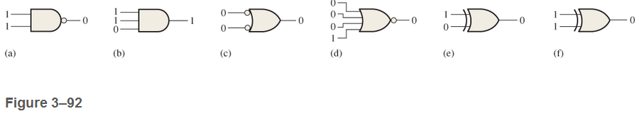
Examine the conditions indicated in Figure 3-92, and identify the faulty gates
Expert Solution & Answer
Want to see the full answer?
Check out a sample textbook solution
Students have asked these similar questions
1- A combinational circuit is defined by the following three functions:
F1= XY + XYZ
F2= XY + XYZ
F3- XỸZ + 7Z
Design the circuit with a decoder and external gates.
List four common internal failures in logic gates
2. Design a full adder and a full subtractor using minimum number of two-input NAND
and two-input XOR gates. Show how you can use half adders and half subtractors to build a full
adder and full subtractor. Show and explain your designs in detail.
Chapter 3 Solutions
Digital Fundamentals (11th Edition)
Ch. 3.1 - When a 1 is on the input of an inverter, what is...Ch. 3.1 - An active-HIGH pulse (HIGH level when asserted,...Ch. 3.2 - When is the output of an AND gate HIGH?Ch. 3.2 - When is the output of an AND gate LOW?Ch. 3.2 - Describe the truth table for a 5-input AND gate.Ch. 3.3 - When is the output of an OR gate HIGH?Ch. 3.3 - When is the output of an OR gate LOW?Ch. 3.3 - Describe the truth table for a 3-input OR gate.Ch. 3.4 - When is the output of a NAND gate LOW?Ch. 3.4 - When is the output of a NAND gate HIGH?
Ch. 3.4 - Describe the functional differences between a NAND...Ch. 3.4 - Write the output expression for a NAND gate with...Ch. 3.5 - When is the output of a NOR gate HIGH?Ch. 3.5 - When is the output of a NOR gate LOW?Ch. 3.5 - Describe the functional difference between a NOR...Ch. 3.5 - Write the output expression for a 3-input NOR with...Ch. 3.6 - When is the output of an XOR gate HIGH?Ch. 3.6 - When is the output of an XNOR gate HIGH?Ch. 3.6 - How can you use an XOR gate to detect when two...Ch. 3.7 - List six process technologies used for...Ch. 3.7 - What does the term volatile mean in relation to...Ch. 3.7 - What are two design entry methods for programming...Ch. 3.7 - Prob. 4CUCh. 3.7 - Write a VHDL description of a 3-input NOR gate,Ch. 3.7 - Write a VHDL description of an XOR gate.Ch. 3.8 - How is fixed-function logic different than PLD...Ch. 3.8 - Prob. 2CUCh. 3.8 - Identify the following IC logic designators: LS HC...Ch. 3.8 - Prob. 4CUCh. 3.8 - What does the term hex inverter mean? What does...Ch. 3.8 - A positive pulse is applied to an inverter input....Ch. 3.8 - A certain gate has a propagation delay time of 6...Ch. 3.8 - Prob. 8CUCh. 3.8 - Prob. 9CUCh. 3.8 - Prob. 10CUCh. 3.9 - Prob. 1CUCh. 3.9 - If two different input waveforms are applied to a...Ch. 3.9 - Prob. 3CUCh. 3 - An inverter performs the NOR operation.Ch. 3 - An AND gate can have only two inputsCh. 3 - If any input to an OR is 1, the output is 1.Ch. 3 - If all inputs to an AND gate are 1, the output is...Ch. 3 - A NAND gate has an output that is opposite the...Ch. 3 - A NOR gate can be considered as an OR gate...Ch. 3 - The output of an exclusive-OR is 0 if the inputs...Ch. 3 - Prob. 8TFQCh. 3 - Once programmed, PLD logic can be changed.Ch. 3 - Fan-out is the number of similar gates that a...Ch. 3 - When the input to an inverter is HIGH (1), the...Ch. 3 - An inverter performs an operation known as...Ch. 3 - The output of an AND gate with inputs A, B, and C...Ch. 3 - The output of an OR gate with inputs A, B, and C...Ch. 3 - A pulse is applied to each input of a 2-input NAND...Ch. 3 - A pulse is applied to each input of a 2-input NOR...Ch. 3 - A pulse is applied to each input of an...Ch. 3 - Prob. 8STCh. 3 - The purpose of a programmable link in an AND array...Ch. 3 - The term OTP means open test point one-time...Ch. 3 - Prob. 11STCh. 3 - Prob. 12STCh. 3 - Two ways to enter a logic design using PLD...Ch. 3 - Prob. 14STCh. 3 - In-system programming of a PLD typically utilizes...Ch. 3 - To measure the period of a pulse waveform, you...Ch. 3 - Prob. 17STCh. 3 - The input waveform shown in Figure 3-76 is applied...Ch. 3 - A combination of inverters is shown in Figure...Ch. 3 - If the waveform in Figure 3-76 is applied to point...Ch. 3 - Draw the rectangular outline symbol for a 4-input...Ch. 3 - Determine the output, X, for a 2-input AND gate...Ch. 3 - Repeat problem 5 for the waveforms in Figure 3-79Ch. 3 - The input wave forms applied to a 3-input AND gate...Ch. 3 - The input waveforms applied to a 4-input AND gate...Ch. 3 - Draw the rectangular outline symbol for a 3-input...Ch. 3 - Write the expression for a 5-input OR gate with...Ch. 3 - Determine the output for a 2-input OR gate when...Ch. 3 - Repeat Problem 7 for a 3-input OR gate.Ch. 3 - Repeat Problem 8 for a 4-input OR gate.Ch. 3 - For the five input waveforms in Figure 3-8219,...Ch. 3 - Draw the rectangular outline symbol for a 4-input...Ch. 3 - Show the truth table for a 3-input OR gate.Ch. 3 - For the set of input waveforms in Figure 3-83,...Ch. 3 - Determine the gate output for the input waveforms...Ch. 3 - Determine the output waveform in Figure 3-8513Ch. 3 - As you have learned, the two logic symbols shown...Ch. 3 - Repeat Problem 17 for a 2-input NOR gate.Ch. 3 - Determine the output waveform in Figure 3-87 and...Ch. 3 - Repeat Problem 19 for a 4-input NOR gate.Ch. 3 - The NAND and the negative-OR symbols represent...Ch. 3 - How does an exclusive-OR gate differ from an OR...Ch. 3 - Repeat Problem 17 for an exclusive-OR gate.Ch. 3 - Repeat Problem 17 for an exclusive-NOR gateCh. 3 - Determine the output of an exclusive-OR gate for...Ch. 3 - In the simple programmed AND array with...Ch. 3 - Determine by row and column number which fusible...Ch. 3 - Describe a 4-input AND gate using VHDL.Ch. 3 - Describe a 5-input NOR gate using VHDLCh. 3 - In the comparison of certain logic devices, it is...Ch. 3 - Prob. 34PCh. 3 - Determine tPLHandtPHL from the oscilloscope...Ch. 3 - Prob. 36PCh. 3 - If a logic gate operates on a dc supply voltage of...Ch. 3 - The variable ICCH represents the dc supply current...Ch. 3 - Examine the conditions indicated in Figure 3-92,...Ch. 3 - Determine the faulty gates in Figure 3-93 by...Ch. 3 - Using an oscilloscope, you make the observations...Ch. 3 - Prob. 42PCh. 3 - Every time the ignition switch is turned on in the...Ch. 3 - What failure(s) would you suspect if the output of...Ch. 3 - Modify the frequency counter in Figure 3-16 to...Ch. 3 - Prob. 46PCh. 3 - Design a circuit to fit in the beige block of...Ch. 3 - Modify the logic circuit for the intrusion alarm...Ch. 3 - Further modify the logic circuit from Problem 48...Ch. 3 - Sensors are used to monitor the pressure and the...Ch. 3 - In a certain automated manufacturing process,...Ch. 3 - Open file P03-52. For the specified fault, predict...Ch. 3 - Open file P03-53. For the specified fault, predict...Ch. 3 - Open file P03-54. For the observed behavior...Ch. 3 - Open file P03-55. For the observed behavior...
Additional Engineering Textbook Solutions
Find more solutions based on key concepts
The code for a library function must appear in a program in order for the program to call the library function.
Starting Out with Programming Logic and Design (4th Edition)
Write a program that determines the change to be dispensed from a vending machine. An item in the machine can c...
Absolute Java (6th Edition)
A criticism of the break statement and the continue statement is that each is unstructured. Actually, break sta...
C How to Program (8th Edition)
Modify Problem and Exercise 6-60 so that the list includes the number of products each customer bought in each ...
Modern Database Management (12th Edition)
A(n) ______ loop has no way of ending and repeats until the program is interrupted. a. indeterminate b. intermi...
Starting Out with Programming Logic and Design (5th Edition) (What's New in Computer Science)
Knowledge Booster


Learn more about
Need a deep-dive on the concept behind this application? Look no further. Learn more about this topic, computer-science and related others by exploring similar questions and additional content below.Similar questions
- Question 5: Predict how the operation of this relay logic circuit will be affected as a result of the following faults. Consider each fault independently (i.e. one at a time, no multiple faults): L1 L2 A CR1 B CR2 it CR1-1 CR3 CR2-1 CR3-1 Lamp 1 CR1-2 CR2-2 Lamp 2 Pushbutton switch A fails open: Relay coil CR2 fails open: Relay contact CR1-1 fails open: Relay contact CR2-1 fails shorted: Relay contact CR2-2 fails shorted: For each of these conditions, explain why the resulting effects will occur.arrow_forwardWrite the Boolean expression for a four-input NAND gate and apply DeMorgan theorem. Draw the circuit diagram of four-input NAND gate using two input NAND gates. You may need additional logic gates to complete the diagram.arrow_forwardPROBLEM NO.1 (odd numbers) Design a Gray code converter to drive a seven-segment indicator. The four inputs to the converter circuit (A, B, C, and D in Figure 1) represent a decimal digit coded using the Gray code. Assume that only input combinations representing the digits 0 through 9 can occur as inputs, so that the six unused combinations are don't-care terms. Design your circuit using only two-, three-, and four-input NAND gates and inverters. Try to minimize the numbers of gates and inverters required. The variables A, B, C, and D will be available from toggle switches. 6 (not) for 6. Use 9 (not 9 ) for 9. Figure 1 Any solution with 20 or fewer gates and inverters (not counting the four inverters for the inputs) isarrow_forward
- Step by step Simplify according to the rules and design before and after logic gates along with truth table. f(x,y,z)=x'yz+xy'z+xyz'+xyzarrow_forwardTask 1 According to the given truth table construct function and implement the circuit on logical gates: x1 x2 x3 x4 Y 0 0 0 0 1 0 0 1 0 0 1 0 0 0 0 1 1 1 0 1 0 0 1 1 0 1 1 0 1 1 1 0 1 1 0 1 0 1 1 0 1 0 1 1 0 1 1 1 1 1 1 1 1 1 HOOH 0 0 1 1 OHOHOHOHOH 0 1 0 1 0 1 0 1 0 1 OH OH HOO 0 1 0 1 1arrow_forward1. Design a simple logic circuit for a Set/Reset (SR) Latch, based on any actual application of latches. 2.) Describe your design using at least three (4) sentences. Note: Look at the example guide on the image.arrow_forward
- 1) Design a circuit that implements the behavior of an XOR-gate, using only NAND-gates. 2) Verify your design by constructing a truth table for it. 3) Verify whether the behavior of the circuit matches the truth table.arrow_forwardSuppose, the password for a security lock system is 5-digit in length and consists of binary digits only. Design an optimized circuit using basic logic gates only for the system which opens the lock when there are even number of 1’s in the password. Show your work in detail and draw circuit diagram neatly for the lock system.arrow_forwardThe connection diagram shows multiple gates and the pins assigned to each gate. For example, from the datasheet connection diagram of IC 7400, four individual NAND gates can be observed. Pins 1, 2 and 3 are all related to one of the four NAND gates. For each gate the top input is assigned the letter A while the bottom input is assigned B and the output is assigned the letter Y. The function tables of the ICs are normally given in terms of H (High logic level) and L (Low logic level). Referring to the datasheet function table of IC 7400 shows the four different input combinations of A and B and the corresponding output Y for one of the four NAND gates. There is also one more letter assignment that could be found in function tables, this is the letter X, a don't care assignment. In cases where an X is given, it can be replaced by either an H or L assignment without effecting the resultant functionality of the IC. An example of this case can be seen for the function table of IC 7402. The…arrow_forward
- determine the output (in terms of Boolean expressions) of all four logic gates in the circuit.arrow_forwardrefer to image below. Redraw the logic diagram using only NAND gates.arrow_forwardDesign a comparator to compare two eight bit numbers? Draw complete gate level diagram? Note: Draw a diagram which show gates aswell diagram like this(shown in picture) is not requiredarrow_forward
arrow_back_ios
SEE MORE QUESTIONS
arrow_forward_ios
Recommended textbooks for you
 Database System ConceptsComputer ScienceISBN:9780078022159Author:Abraham Silberschatz Professor, Henry F. Korth, S. SudarshanPublisher:McGraw-Hill Education
 Starting Out with Python (4th Edition)Computer ScienceISBN:9780134444321Author:Tony GaddisPublisher:PEARSON
 Digital Fundamentals (11th Edition)Computer ScienceISBN:9780132737968Author:Thomas L. FloydPublisher:PEARSON
 C How to Program (8th Edition)Computer ScienceISBN:9780133976892Author:Paul J. Deitel, Harvey DeitelPublisher:PEARSON
 Database Systems: Design, Implementation, & Manag...Computer ScienceISBN:9781337627900Author:Carlos Coronel, Steven MorrisPublisher:Cengage Learning
 Programmable Logic ControllersComputer ScienceISBN:9780073373843Author:Frank D. PetruzellaPublisher:McGraw-Hill Education
Database System Concepts
Computer Science
ISBN:9780078022159
Author:Abraham Silberschatz Professor, Henry F. Korth, S. Sudarshan
Publisher:McGraw-Hill Education
Starting Out with Python (4th Edition)
Computer Science
ISBN:9780134444321
Author:Tony Gaddis
Publisher:PEARSON
Digital Fundamentals (11th Edition)
Computer Science
ISBN:9780132737968
Author:Thomas L. Floyd
Publisher:PEARSON
C How to Program (8th Edition)
Computer Science
ISBN:9780133976892
Author:Paul J. Deitel, Harvey Deitel
Publisher:PEARSON
Database Systems: Design, Implementation, & Manag...
Computer Science
ISBN:9781337627900
Author:Carlos Coronel, Steven Morris
Publisher:Cengage Learning
Programmable Logic Controllers
Computer Science
ISBN:9780073373843
Author:Frank D. Petruzella
Publisher:McGraw-Hill Education
Boolean Algebra - Digital Logic and Logic Families - Industrial Electronics; Author: Ekeeda;https://www.youtube.com/watch?v=u7XnJos-_Hs;License: Standard YouTube License, CC-BY
Boolean Algebra 1 – The Laws of Boolean Algebra; Author: Computer Science;https://www.youtube.com/watch?v=EPJf4owqwdA;License: Standard Youtube License