
Digital Fundamentals (11th Edition)
11th Edition
ISBN: 9780132737968
Author: Thomas L. Floyd
Publisher: PEARSON
expand_more
expand_more
format_list_bulleted
Videos
Textbook Question
Chapter 3, Problem 40P
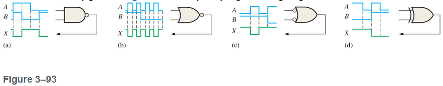
Determine the faulty gates in Figure 3-93 by analyzing the timing diagrams.
Expert Solution & Answer
Want to see the full answer?
Check out a sample textbook solution
Students have asked these similar questions
This is a question that I have and would like someone who has experiences with scene graphs and entity component systems to answer.For context, I am currently implementing a game engine and currently I am debating on our current design.Our current design is we have a singular game component class that every component inherits from. Where we have components like SpriteRendererComponent, Mehs Component, etc. They inherit from this GameComponent class. The point of this is being able to have O(1) access to the scene to being able to modify components to attach more components with the idea of accessing those components to specific scene objects in a scene.Now, my question is what kinds of caveauts can this cause in terms of cache coherence? I am well aware that yes its O(1) and that is great but cache coherence is going to be really bad, but would like to know more explicit details and real-life examples such as write in RAM examples on how this is bad. A follow-up question that is part…
Q4: Consider the following MAILORDER relational schema describing the data for a mail order
company. (Choose five only).
PARTS(Pno, Pname, Qoh, Price, Olevel)
CUSTOMERS(Cno, Cname, Street, Zip, Phone)
EMPLOYEES(Eno, Ename, Zip, Hdate)
ZIP CODES(Zip, City)
ORDERS(Ono, Cno, Eno, Received, Shipped)
ODETAILS(Ono, Pno, Qty)
(10 Marks)
I want a detailed explanation to
understand the mechanism how it is
Qoh stands for quantity on hand: the other attribute names are self-explanatory. Specify and
execute the following queries using the RA interpreter on the MAILORDER database schema.
a. Retrieve the names of parts that cost less than $20.00.
b. Retrieve the names and cities of employees who have taken orders for parts costing more than
$50.00.
c. Retrieve the pairs of customer number values of customers who live in the same ZIP Code.
d. Retrieve the names of customers who have ordered parts from employees living in Wichita.
e. Retrieve the names of customers who have ordered parts costing less…
Q4: Consider the following MAILORDER relational schema describing the data for a mail order
company. (Choose five only).
(10 Marks)
PARTS(Pno, Pname, Qoh, Price, Olevel)
CUSTOMERS(Cno, Cname, Street, Zip, Phone)
EMPLOYEES(Eno, Ename, Zip, Hdate)
ZIP CODES(Zip, City)
ORDERS(Ono, Cno, Eno, Received, Shipped)
ODETAILS(Ono, Pno, Qty)
Qoh stands for quantity on hand: the other attribute names are self-explanatory. Specify and
execute the following queries using the RA interpreter on the MAILORDER database schema.
a. Retrieve the names of parts that cost less than $20.00.
b. Retrieve the names and cities of employees who have taken orders for parts costing more than
$50.00.
c. Retrieve the pairs of customer number values of customers who live in the same ZIP Code.
d. Retrieve the names of customers who have ordered parts from employees living in Wichita.
e. Retrieve the names of customers who have ordered parts costing less than$20.00.
f. Retrieve the names of customers who have not placed…
Chapter 3 Solutions
Digital Fundamentals (11th Edition)
Ch. 3.1 - When a 1 is on the input of an inverter, what is...Ch. 3.1 - An active-HIGH pulse (HIGH level when asserted,...Ch. 3.2 - When is the output of an AND gate HIGH?Ch. 3.2 - When is the output of an AND gate LOW?Ch. 3.2 - Describe the truth table for a 5-input AND gate.Ch. 3.3 - When is the output of an OR gate HIGH?Ch. 3.3 - When is the output of an OR gate LOW?Ch. 3.3 - Describe the truth table for a 3-input OR gate.Ch. 3.4 - When is the output of a NAND gate LOW?Ch. 3.4 - When is the output of a NAND gate HIGH?
Ch. 3.4 - Describe the functional differences between a NAND...Ch. 3.4 - Write the output expression for a NAND gate with...Ch. 3.5 - When is the output of a NOR gate HIGH?Ch. 3.5 - When is the output of a NOR gate LOW?Ch. 3.5 - Describe the functional difference between a NOR...Ch. 3.5 - Write the output expression for a 3-input NOR with...Ch. 3.6 - When is the output of an XOR gate HIGH?Ch. 3.6 - When is the output of an XNOR gate HIGH?Ch. 3.6 - How can you use an XOR gate to detect when two...Ch. 3.7 - List six process technologies used for...Ch. 3.7 - What does the term volatile mean in relation to...Ch. 3.7 - What are two design entry methods for programming...Ch. 3.7 - Prob. 4CUCh. 3.7 - Write a VHDL description of a 3-input NOR gate,Ch. 3.7 - Write a VHDL description of an XOR gate.Ch. 3.8 - How is fixed-function logic different than PLD...Ch. 3.8 - Prob. 2CUCh. 3.8 - Identify the following IC logic designators: LS HC...Ch. 3.8 - Prob. 4CUCh. 3.8 - What does the term hex inverter mean? What does...Ch. 3.8 - A positive pulse is applied to an inverter input....Ch. 3.8 - A certain gate has a propagation delay time of 6...Ch. 3.8 - Prob. 8CUCh. 3.8 - Prob. 9CUCh. 3.8 - Prob. 10CUCh. 3.9 - Prob. 1CUCh. 3.9 - If two different input waveforms are applied to a...Ch. 3.9 - Prob. 3CUCh. 3 - An inverter performs the NOR operation.Ch. 3 - An AND gate can have only two inputsCh. 3 - If any input to an OR is 1, the output is 1.Ch. 3 - If all inputs to an AND gate are 1, the output is...Ch. 3 - A NAND gate has an output that is opposite the...Ch. 3 - A NOR gate can be considered as an OR gate...Ch. 3 - The output of an exclusive-OR is 0 if the inputs...Ch. 3 - Prob. 8TFQCh. 3 - Once programmed, PLD logic can be changed.Ch. 3 - Fan-out is the number of similar gates that a...Ch. 3 - When the input to an inverter is HIGH (1), the...Ch. 3 - An inverter performs an operation known as...Ch. 3 - The output of an AND gate with inputs A, B, and C...Ch. 3 - The output of an OR gate with inputs A, B, and C...Ch. 3 - A pulse is applied to each input of a 2-input NAND...Ch. 3 - A pulse is applied to each input of a 2-input NOR...Ch. 3 - A pulse is applied to each input of an...Ch. 3 - Prob. 8STCh. 3 - The purpose of a programmable link in an AND array...Ch. 3 - The term OTP means open test point one-time...Ch. 3 - Prob. 11STCh. 3 - Prob. 12STCh. 3 - Two ways to enter a logic design using PLD...Ch. 3 - Prob. 14STCh. 3 - In-system programming of a PLD typically utilizes...Ch. 3 - To measure the period of a pulse waveform, you...Ch. 3 - Prob. 17STCh. 3 - The input waveform shown in Figure 3-76 is applied...Ch. 3 - A combination of inverters is shown in Figure...Ch. 3 - If the waveform in Figure 3-76 is applied to point...Ch. 3 - Draw the rectangular outline symbol for a 4-input...Ch. 3 - Determine the output, X, for a 2-input AND gate...Ch. 3 - Repeat problem 5 for the waveforms in Figure 3-79Ch. 3 - The input wave forms applied to a 3-input AND gate...Ch. 3 - The input waveforms applied to a 4-input AND gate...Ch. 3 - Draw the rectangular outline symbol for a 3-input...Ch. 3 - Write the expression for a 5-input OR gate with...Ch. 3 - Determine the output for a 2-input OR gate when...Ch. 3 - Repeat Problem 7 for a 3-input OR gate.Ch. 3 - Repeat Problem 8 for a 4-input OR gate.Ch. 3 - For the five input waveforms in Figure 3-8219,...Ch. 3 - Draw the rectangular outline symbol for a 4-input...Ch. 3 - Show the truth table for a 3-input OR gate.Ch. 3 - For the set of input waveforms in Figure 3-83,...Ch. 3 - Determine the gate output for the input waveforms...Ch. 3 - Determine the output waveform in Figure 3-8513Ch. 3 - As you have learned, the two logic symbols shown...Ch. 3 - Repeat Problem 17 for a 2-input NOR gate.Ch. 3 - Determine the output waveform in Figure 3-87 and...Ch. 3 - Repeat Problem 19 for a 4-input NOR gate.Ch. 3 - The NAND and the negative-OR symbols represent...Ch. 3 - How does an exclusive-OR gate differ from an OR...Ch. 3 - Repeat Problem 17 for an exclusive-OR gate.Ch. 3 - Repeat Problem 17 for an exclusive-NOR gateCh. 3 - Determine the output of an exclusive-OR gate for...Ch. 3 - In the simple programmed AND array with...Ch. 3 - Determine by row and column number which fusible...Ch. 3 - Describe a 4-input AND gate using VHDL.Ch. 3 - Describe a 5-input NOR gate using VHDLCh. 3 - In the comparison of certain logic devices, it is...Ch. 3 - Prob. 34PCh. 3 - Determine tPLHandtPHL from the oscilloscope...Ch. 3 - Prob. 36PCh. 3 - If a logic gate operates on a dc supply voltage of...Ch. 3 - The variable ICCH represents the dc supply current...Ch. 3 - Examine the conditions indicated in Figure 3-92,...Ch. 3 - Determine the faulty gates in Figure 3-93 by...Ch. 3 - Using an oscilloscope, you make the observations...Ch. 3 - Prob. 42PCh. 3 - Every time the ignition switch is turned on in the...Ch. 3 - What failure(s) would you suspect if the output of...Ch. 3 - Modify the frequency counter in Figure 3-16 to...Ch. 3 - Prob. 46PCh. 3 - Design a circuit to fit in the beige block of...Ch. 3 - Modify the logic circuit for the intrusion alarm...Ch. 3 - Further modify the logic circuit from Problem 48...Ch. 3 - Sensors are used to monitor the pressure and the...Ch. 3 - In a certain automated manufacturing process,...Ch. 3 - Open file P03-52. For the specified fault, predict...Ch. 3 - Open file P03-53. For the specified fault, predict...Ch. 3 - Open file P03-54. For the observed behavior...Ch. 3 - Open file P03-55. For the observed behavior...
Additional Engineering Textbook Solutions
Find more solutions based on key concepts
Determine the resultant internal normal force, shear force, and bending moment at point C in the beam.
Mechanics of Materials (10th Edition)
In Exercises 41 through 46, identify the errors.
Introduction To Programming Using Visual Basic (11th Edition)
Identify and correct the errors in each of the following code segments assume that all variables have been prop...
Java How to Program, Early Objects (11th Edition) (Deitel: How to Program)
What is the purpose of the let constructs in functional languages?
Concepts Of Programming Languages
16. In a simple electric circuit, the current (I) must remain below 40 milliarr.ps (I < 40 mA) and must also sa...
Thinking Like an Engineer: An Active Learning Approach (4th Edition)
Knowledge Booster


Learn more about
Need a deep-dive on the concept behind this application? Look no further. Learn more about this topic, computer-science and related others by exploring similar questions and additional content below.Similar questions
- ut da Q4: Consider the LIBRARY relational database schema shown in Figure below a. Edit Author_name to new variable name where previous surname was 'Al - Wazny'. Update book_Authors set Author_name = 'alsaadi' where Author_name = 'Al - Wazny' b. Change data type of Phone to string instead of numbers. عرفنه شنو الحل BOOK Book id Title Publisher_name BOOK AUTHORS Book id Author_name PUBLISHER Name Address Phone e u al b are rage c. Add two Publishers Company existed in UK. insert into publisher(name, address, phone) value('ali','uk',78547889), ('karrar', 'uk', 78547889) d. Remove all books author when author name contains second character 'D' and ending by character 'i'. es inf rmar nce 1 tic عرفته شنو الحل e. Add one book as variables data? عرفته شنو الحلarrow_forwardAdd a timer in the following code. public class GameGUI extends JPanel { private final Labyrinth labyrinth; private final Player player; private final Dragon dragon; private Timer timer; private long elapsedTime; public GameGUI(Labyrinth labyrinth, Player player, Dragon dragon) { this.labyrinth = labyrinth; this.player = player; this.dragon = dragon; String playerName = JOptionPane.showInputDialog("Enter your name:"); player.setName(playerName); elapsedTime = 0; timer = new Timer(1000, e -> { elapsedTime++; repaint(); }); timer.start(); } @Override protected void paintComponent(Graphics g) { super.paintComponent(g); int cellSize = Math.min(getWidth() / labyrinth.getSize(), getHeight() / labyrinth.getSize());}arrow_forwardChange the following code so that when player wins the game, the game continues by creating new GameGUI with the same player. However the player's starting position is same, everything else should be reseted. public static void main(String[] args) { Labyrinth labyrinth = new Labyrinth(10); Player player = new Player(9, 0); Random rand = new Random(); Dragon dragon = new Dragon(rand.nextInt(10), 9); JFrame frame = new JFrame("Labyrinth Game"); GameGUI gui = new GameGUI(labyrinth, player, dragon); frame.setLayout(new BorderLayout()); frame.setSize(600, 600); frame.setDefaultCloseOperation(JFrame.EXIT_ON_CLOSE); frame.add(gui, BorderLayout.CENTER); frame.pack(); frame.setResizable(false); frame.setVisible(true); } public class GameGUI extends JPanel { private final Labyrinth labyrinth; private final Player player; private final Dragon dragon; private Timer timer; private long…arrow_forward
- Create a menu item which restarts the game. Also add a timer, which counts the elapsed time since the start of the game level. When the restart is pressed, the restarted game should ask the player' name (in the GameGUI constructor) and set the score of player to 0 (player.setScore(0)), and the timer should restart again. And create a logic so that if the player loses his life (checkGame if the condition is false), then save this number together with his name into two variables. And display two buttons where one quits the game altogether (System.exit(0)) and the other restarts the game. public class GameGUI extends JPanel { private final Labyrinth labyrinth; private final Player player; private final Dragon dragon; private final ImageIcon playerIcon = new ImageIcon("data/images/player.png"); private final ImageIcon dragonIcon = new ImageIcon("data/images/dragon.png"); private final ImageIcon wallIcon = new ImageIcon("data/images/wall.png"); private final ImageIcon…arrow_forwardPlease original work Analyze the complexity issues of processing big data What are five complexities and talk about the reasons they make the implementation complex. Please cite in text references and add weblinksarrow_forwardCreate a Database in JAVA Netbeans that saves name of the player and how many labyrinths did the player solve. Record the number of how many labyrinths did the player solve, and if he loses his life, then save this number together with his name into the database. Create a menu item, which displays a highscore table of the players for the 10 best scores public class GameGUI extends JPanel { private final Labyrinth labyrinth; private final Player player; private final Dragon dragon; private void checkGameState() { if (player.getX() == 0 && player.getY() == labyrinth.getSize() - 1) { JOptionPane.showMessageDialog(this, "You escaped! Congratulations!"); System.exit(0); } if (Math.abs(player.getX() - dragon.getX()) <= 1 && Math.abs(player.getY() - dragon.getY()) <= 1) { JOptionPane.showMessageDialog(this, "The dragon caught you! Game Over."); System.exit(0); } } } public…arrow_forward
- Create a Database in JAVA OOP that saves name of the player and how many labyrinths did the player solve. Record the number of how many labyrinths did the player solve, and if he loses his life, then save this number together with his name into the database. Create a menu item, which displays a highscore table of the players for the 10 best scores. Also, create a menu item which restarts the game. public class GameGUI extends JPanel { private final Labyrinth labyrinth; private final Player player; private final Dragon dragon; private void checkGameState() { if (player.getX() == 0 && player.getY() == labyrinth.getSize() - 1) { JOptionPane.showMessageDialog(this, "You escaped! Congratulations!"); System.exit(0); } if (Math.abs(player.getX() - dragon.getX()) <= 1 && Math.abs(player.getY() - dragon.getY()) <= 1) { JOptionPane.showMessageDialog(this, "The dragon caught you! Game Over.");…arrow_forwardChange the following code so that the player can see only the neighboring fields at a distance of 3 units. public class GameGUI extends JPanel { private final Labyrinth labyrinth; private final Player player; private final Dragon dragon; private final ImageIcon playerIcon = new ImageIcon("data/images/player.png"); private final ImageIcon dragonIcon = new ImageIcon("data/images/dragon.png"); private final ImageIcon wallIcon = new ImageIcon("data/images/wall.png"); private final ImageIcon emptyIcon = new ImageIcon("data/images/empty.png"); public GameGUI(Labyrinth labyrinth, Player player, Dragon dragon) { this.labyrinth = labyrinth; this.player = player; this.dragon = dragon; setFocusable(true); addKeyListener(new KeyAdapter() { @Override public void keyPressed(KeyEvent e) { char move = switch (e.getKeyCode()) { case KeyEvent.VK_W -> 'W'; case…arrow_forwardQ/ Fill in the table below with the correct answers for the network devices and components required, then draw the topology diagram for the network of this three-story building: I want a drawing Cisco Packet tracer Ground Floor: This floor will house the main server room, reception area, and a few conference rooms. The server room should contain the core network devices that will connect the entire building. The reception area and conference rooms need network access require access for mobile devices for visitors and guests with devices. First Floor: This floor is dedicated to offices with workstations, each needing reliable network connectivity for staff computers, IP phones, IP camera, and printers. Second Floor (Education Department): This floor consists of educational spaces requiring controlled internet access. Only the educational website (https://uokerbala.edu.iq) should be accessible, with all other sites restricted.. Device Media type Location floor Type of IP Static/dynamic…arrow_forward
- Problem Statement You are working as a Devops Administrator. Y ou’ve been t asked to deploy a multi - tier application on Kubernetes Cluster. The application is a NodeJS application available on Docker Hub with the following name: d evopsedu/emp loyee This Node JS application works with a mongo database. MongoDB image is available on D ockerHub with the following name: m ongo You are required to deploy this application on Kubernetes: • NodeJS is available on port 8888 in the container and will be reaching out to por t 27017 for mongo database connection • MongoDB will be accepting connections on port 27017 You must deploy this application using the CL I . Once your application is up and running, ensure you can add an employee from the NodeJS application and verify by going to Get Employee page and retrieving your input. Hint: Name the Mongo DB Service and deployment, specifically as “mongo”.arrow_forwardI need help in server client project. It is around 1200 lines of code in both . I want to meet with the expert online because it is complicated. I want the server send a menu to the client and the client enters his choice and keep on this until the client chooses to exit . the problem is not in the connection itself as far as I know.I tried while loops but did not work. please help its emergentarrow_forwardI need help in my server client in C languagearrow_forward
arrow_back_ios
SEE MORE QUESTIONS
arrow_forward_ios
Recommended textbooks for you
 Database System ConceptsComputer ScienceISBN:9780078022159Author:Abraham Silberschatz Professor, Henry F. Korth, S. SudarshanPublisher:McGraw-Hill Education
 Starting Out with Python (4th Edition)Computer ScienceISBN:9780134444321Author:Tony GaddisPublisher:PEARSON
 Digital Fundamentals (11th Edition)Computer ScienceISBN:9780132737968Author:Thomas L. FloydPublisher:PEARSON
 C How to Program (8th Edition)Computer ScienceISBN:9780133976892Author:Paul J. Deitel, Harvey DeitelPublisher:PEARSON
 Database Systems: Design, Implementation, & Manag...Computer ScienceISBN:9781337627900Author:Carlos Coronel, Steven MorrisPublisher:Cengage Learning
 Programmable Logic ControllersComputer ScienceISBN:9780073373843Author:Frank D. PetruzellaPublisher:McGraw-Hill Education
Database System Concepts
Computer Science
ISBN:9780078022159
Author:Abraham Silberschatz Professor, Henry F. Korth, S. Sudarshan
Publisher:McGraw-Hill Education
Starting Out with Python (4th Edition)
Computer Science
ISBN:9780134444321
Author:Tony Gaddis
Publisher:PEARSON
Digital Fundamentals (11th Edition)
Computer Science
ISBN:9780132737968
Author:Thomas L. Floyd
Publisher:PEARSON
C How to Program (8th Edition)
Computer Science
ISBN:9780133976892
Author:Paul J. Deitel, Harvey Deitel
Publisher:PEARSON
Database Systems: Design, Implementation, & Manag...
Computer Science
ISBN:9781337627900
Author:Carlos Coronel, Steven Morris
Publisher:Cengage Learning
Programmable Logic Controllers
Computer Science
ISBN:9780073373843
Author:Frank D. Petruzella
Publisher:McGraw-Hill Education
Boolean Algebra - Digital Logic and Logic Families - Industrial Electronics; Author: Ekeeda;https://www.youtube.com/watch?v=u7XnJos-_Hs;License: Standard YouTube License, CC-BY
Boolean Algebra 1 – The Laws of Boolean Algebra; Author: Computer Science;https://www.youtube.com/watch?v=EPJf4owqwdA;License: Standard Youtube License