
Digital Fundamentals (11th Edition)
11th Edition
ISBN: 9780132737968
Author: Thomas L. Floyd
Publisher: PEARSON
expand_more
expand_more
format_list_bulleted
Videos
Textbook Question
Chapter 3, Problem 35P
Determine
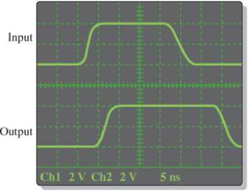
Figure 3-91
Expert Solution & Answer
Want to see the full answer?
Check out a sample textbook solution
Students have asked these similar questions
The period of a pulse waveform measures four horizontal divisions on an oscilloscope. If the time base is set at 2 ms/div, what is the frequency of the waveform?
7. Connect the biased positive clamping circuit shown in Fig.12, and apply a 10Vpp sinusoidal
input waveform with frequency of 1 kHz at the input. Display and sketch the input and the
output waveforms.
CH1
CH2
10 μF
D,
1N4007
RL
Vin
Vout
68k
10Vpp
f=1 kHz
VB
5V
GND
Figure 12: Practical Biased Positive Clamping Circuit
From the circuit below, Calculate
A. Frequency of Oscillation
B. Period of Oscillation
Chapter 3 Solutions
Digital Fundamentals (11th Edition)
Ch. 3.1 - When a 1 is on the input of an inverter, what is...Ch. 3.1 - An active-HIGH pulse (HIGH level when asserted,...Ch. 3.2 - When is the output of an AND gate HIGH?Ch. 3.2 - When is the output of an AND gate LOW?Ch. 3.2 - Describe the truth table for a 5-input AND gate.Ch. 3.3 - When is the output of an OR gate HIGH?Ch. 3.3 - When is the output of an OR gate LOW?Ch. 3.3 - Describe the truth table for a 3-input OR gate.Ch. 3.4 - When is the output of a NAND gate LOW?Ch. 3.4 - When is the output of a NAND gate HIGH?
Ch. 3.4 - Describe the functional differences between a NAND...Ch. 3.4 - Write the output expression for a NAND gate with...Ch. 3.5 - When is the output of a NOR gate HIGH?Ch. 3.5 - When is the output of a NOR gate LOW?Ch. 3.5 - Describe the functional difference between a NOR...Ch. 3.5 - Write the output expression for a 3-input NOR with...Ch. 3.6 - When is the output of an XOR gate HIGH?Ch. 3.6 - When is the output of an XNOR gate HIGH?Ch. 3.6 - How can you use an XOR gate to detect when two...Ch. 3.7 - List six process technologies used for...Ch. 3.7 - What does the term volatile mean in relation to...Ch. 3.7 - What are two design entry methods for programming...Ch. 3.7 - Prob. 4CUCh. 3.7 - Write a VHDL description of a 3-input NOR gate,Ch. 3.7 - Write a VHDL description of an XOR gate.Ch. 3.8 - How is fixed-function logic different than PLD...Ch. 3.8 - Prob. 2CUCh. 3.8 - Identify the following IC logic designators: LS HC...Ch. 3.8 - Prob. 4CUCh. 3.8 - What does the term hex inverter mean? What does...Ch. 3.8 - A positive pulse is applied to an inverter input....Ch. 3.8 - A certain gate has a propagation delay time of 6...Ch. 3.8 - Prob. 8CUCh. 3.8 - Prob. 9CUCh. 3.8 - Prob. 10CUCh. 3.9 - Prob. 1CUCh. 3.9 - If two different input waveforms are applied to a...Ch. 3.9 - Prob. 3CUCh. 3 - An inverter performs the NOR operation.Ch. 3 - An AND gate can have only two inputsCh. 3 - If any input to an OR is 1, the output is 1.Ch. 3 - If all inputs to an AND gate are 1, the output is...Ch. 3 - A NAND gate has an output that is opposite the...Ch. 3 - A NOR gate can be considered as an OR gate...Ch. 3 - The output of an exclusive-OR is 0 if the inputs...Ch. 3 - Prob. 8TFQCh. 3 - Once programmed, PLD logic can be changed.Ch. 3 - Fan-out is the number of similar gates that a...Ch. 3 - When the input to an inverter is HIGH (1), the...Ch. 3 - An inverter performs an operation known as...Ch. 3 - The output of an AND gate with inputs A, B, and C...Ch. 3 - The output of an OR gate with inputs A, B, and C...Ch. 3 - A pulse is applied to each input of a 2-input NAND...Ch. 3 - A pulse is applied to each input of a 2-input NOR...Ch. 3 - A pulse is applied to each input of an...Ch. 3 - Prob. 8STCh. 3 - The purpose of a programmable link in an AND array...Ch. 3 - The term OTP means open test point one-time...Ch. 3 - Prob. 11STCh. 3 - Prob. 12STCh. 3 - Two ways to enter a logic design using PLD...Ch. 3 - Prob. 14STCh. 3 - In-system programming of a PLD typically utilizes...Ch. 3 - To measure the period of a pulse waveform, you...Ch. 3 - Prob. 17STCh. 3 - The input waveform shown in Figure 3-76 is applied...Ch. 3 - A combination of inverters is shown in Figure...Ch. 3 - If the waveform in Figure 3-76 is applied to point...Ch. 3 - Draw the rectangular outline symbol for a 4-input...Ch. 3 - Determine the output, X, for a 2-input AND gate...Ch. 3 - Repeat problem 5 for the waveforms in Figure 3-79Ch. 3 - The input wave forms applied to a 3-input AND gate...Ch. 3 - The input waveforms applied to a 4-input AND gate...Ch. 3 - Draw the rectangular outline symbol for a 3-input...Ch. 3 - Write the expression for a 5-input OR gate with...Ch. 3 - Determine the output for a 2-input OR gate when...Ch. 3 - Repeat Problem 7 for a 3-input OR gate.Ch. 3 - Repeat Problem 8 for a 4-input OR gate.Ch. 3 - For the five input waveforms in Figure 3-8219,...Ch. 3 - Draw the rectangular outline symbol for a 4-input...Ch. 3 - Show the truth table for a 3-input OR gate.Ch. 3 - For the set of input waveforms in Figure 3-83,...Ch. 3 - Determine the gate output for the input waveforms...Ch. 3 - Determine the output waveform in Figure 3-8513Ch. 3 - As you have learned, the two logic symbols shown...Ch. 3 - Repeat Problem 17 for a 2-input NOR gate.Ch. 3 - Determine the output waveform in Figure 3-87 and...Ch. 3 - Repeat Problem 19 for a 4-input NOR gate.Ch. 3 - The NAND and the negative-OR symbols represent...Ch. 3 - How does an exclusive-OR gate differ from an OR...Ch. 3 - Repeat Problem 17 for an exclusive-OR gate.Ch. 3 - Repeat Problem 17 for an exclusive-NOR gateCh. 3 - Determine the output of an exclusive-OR gate for...Ch. 3 - In the simple programmed AND array with...Ch. 3 - Determine by row and column number which fusible...Ch. 3 - Describe a 4-input AND gate using VHDL.Ch. 3 - Describe a 5-input NOR gate using VHDLCh. 3 - In the comparison of certain logic devices, it is...Ch. 3 - Prob. 34PCh. 3 - Determine tPLHandtPHL from the oscilloscope...Ch. 3 - Prob. 36PCh. 3 - If a logic gate operates on a dc supply voltage of...Ch. 3 - The variable ICCH represents the dc supply current...Ch. 3 - Examine the conditions indicated in Figure 3-92,...Ch. 3 - Determine the faulty gates in Figure 3-93 by...Ch. 3 - Using an oscilloscope, you make the observations...Ch. 3 - Prob. 42PCh. 3 - Every time the ignition switch is turned on in the...Ch. 3 - What failure(s) would you suspect if the output of...Ch. 3 - Modify the frequency counter in Figure 3-16 to...Ch. 3 - Prob. 46PCh. 3 - Design a circuit to fit in the beige block of...Ch. 3 - Modify the logic circuit for the intrusion alarm...Ch. 3 - Further modify the logic circuit from Problem 48...Ch. 3 - Sensors are used to monitor the pressure and the...Ch. 3 - In a certain automated manufacturing process,...Ch. 3 - Open file P03-52. For the specified fault, predict...Ch. 3 - Open file P03-53. For the specified fault, predict...Ch. 3 - Open file P03-54. For the observed behavior...Ch. 3 - Open file P03-55. For the observed behavior...
Additional Engineering Textbook Solutions
Find more solutions based on key concepts
What names are interrogated by the binary search (Figure 5.14) when searching for the name Joe in the list Alic...
Computer Science: An Overview (12th Edition)
Describe the purpose of the access key attribute and how it supports accessibility.
Web Development and Design Foundations with HTML5 (9th Edition) (What's New in Computer Science)
State which values of the control variable x are printed by each of the following for statements:
C How to Program (8th Edition)
What is a count-controlled loop?
Starting Out with Python (4th Edition)
The acceleration of a Maserati is proportional to the difference between 250 km/h and the velocity of this spor...
Differential Equations: Computing and Modeling (5th Edition), Edwards, Penney & Calvis
Knowledge Booster


Learn more about
Need a deep-dive on the concept behind this application? Look no further. Learn more about this topic, computer-science and related others by exploring similar questions and additional content below.Similar questions
- A signal travels from point A to point B. At point A, the signal power is 300 W. At point B, the power is 280 W. What is the attenuation in decibels?arrow_forwardplease also draw the line for clock signal.arrow_forwardDetermine the voltage of the input signals if the SQR = 40 dB and q=0.2 V.arrow_forward
- Q.5: For the circuit given in Fig.2, determine the output waveforms ( X, Y, and Z) with inputs waveforms A, B, and Cas shown. A Fig.2 В C Y A Barrow_forwardA B 0 MUX S B S This figure, Fig B.3.2, shows the circuit diagram for a two-input multiplexor having inputs A and B, and a control signal S. The equation given in P&H for this circuit is: C = (A*S)+(B*S) This equation is not correct. Please provide the correct equation for this circuit.arrow_forward1. Given ADC0804 and eight LEDS, design an ADC test circuit. Eight LEDS are connected to eight outputs of the ADC, respectively. The output is all 1's when the analog input is 5.1v, and all 0's when the input is Ov. Calculate and make a table indicating analog voltage ranges which correspond to digital number: 00H, 08H, 80H, 88H, and FFH.arrow_forward
- Determine the information capacity in Mbps for a circuit with 100 kHz bandwidth and a signal-to-noise power ratio of 40 dB. (Use 2 decimal places for the final answerarrow_forward1. Connect the clipping circuit shown in Fig. 7, and apply a 20Vpp sinusoidal input waveform with frequency of 1 kHz at the input. Display and sketch both input and output signals. PP CH1 1k2 CH2 R Vin 20V pp f = 1 kHz D1 Vout 1N4007 GND Figure 7: Practical Unbiased Parallel Clipping Circuit 20 ....... ... .... ..... ..... 5.. ..... ..........arrow_forwardAn ABCD-to-seven-segment decoder is a combinational circuit that converts a decimal digit in BCD to an appropriate code for the selection of segments in an indicator used to display the decimal digit in a familiar form. The seven outputs of the decoder (a, b, c, d, e, f, g) select the corresponding segments in the display, as shown in Fig (a). The numeric display chosen to represent the decimal digit is shown in Fig (b). Using a truth table and Karnaugh maps, design the BCD-to-seven-segment decoder using a minimum number of gates. The six invalid combinations should result in a blank display. Please note that this is a different design from what we discussed in the lecture. I 8 d b (a) Segment designation 01:23456789 (b) Numerical designation for display 1) Using the truth table, find the sum-of-minterms for the function for each segment.arrow_forward
- An ABCD-to-seven-segment decoder is a combinational circuit that converts a decimal digit in BCD to an appropriate code for the selection of segments in an indicator used to display the decimal digit in a familiar form. The seven outputs of the decoder (a, b, c, d, e, f, g) select the corresponding segments in the display, as shown in Fig (a). The numeric display chosen to represent the decimal digit is shown in Fig (b). Using a truth table and Karnaugh maps, design the BCD-to-seven-segment decoder using a minimum number of gates. The six invalid combinations should result in a blank display. Please note that this is a different design from what we discussed in the lecture. f e a 8 d b C (a) Segment designation 0123456789 (b) Numerical designation for display 1) Using a Karnaugh map, obtain a minimum sum-of-products form for each segmentarrow_forwardDesign the 7 segment display decoder circuit as shown in the truth table belowarrow_forward3. For RS Flip-Flop shown in Fig. 16b, Find Q waveform for the following inputs waveforms (CK, R, S). 2 3 1 СК 4 5 6 7 8. PR Q CK S CL R (а) (b) Fig. 16arrow_forward
arrow_back_ios
SEE MORE QUESTIONS
arrow_forward_ios
Recommended textbooks for you
 Systems ArchitectureComputer ScienceISBN:9781305080195Author:Stephen D. BurdPublisher:Cengage Learning
Systems Architecture
Computer Science
ISBN:9781305080195
Author:Stephen D. Burd
Publisher:Cengage Learning
Boolean Algebra - Digital Logic and Logic Families - Industrial Electronics; Author: Ekeeda;https://www.youtube.com/watch?v=u7XnJos-_Hs;License: Standard YouTube License, CC-BY
Boolean Algebra 1 – The Laws of Boolean Algebra; Author: Computer Science;https://www.youtube.com/watch?v=EPJf4owqwdA;License: Standard Youtube License