
Videos
(a)
To explain: The effect on voltage drop across each of the resistor when switch opens.
(a)
Answer to Problem 21P
The voltage drop will decrease across the left resistor and the voltage drop is zero across the right resistor. The current through the middle resistor increases with the increase in the voltage drop across it.
Explanation of Solution
Given:
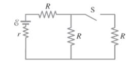
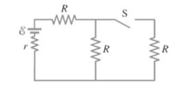
Consider the given circuit.
Formula used:
The equivalent resistance of two series connected resistances is,
The voltage, current and resistance relationship according to Ohm’s law is given by,
Calculation:
The equivalent resistance of the circuit when the switch opens is given by,
The current delivered by the battery is given by,
The equivalent resistance of the circuit when the switch closes is given by,
The current delivered is given by,
When switch is opened, the total current in the circuit decreases due to increase in equivalent resistance of the circuit. So, the voltage drops across the left resistor when switch is opened decreases compared with when switch is closed. From the above discussion, one can conclude that the current through the left resistor decreases, so, the voltage drop across the left resistor decreases. Since, there is no current flow in the right resistor the voltage drop across the right resistor is zero. In parallel combination, the current is shared among the branches. Since, one branch is opened when switch is opened, the current through another branch increases. Thus, the current through middle resistor increases. Corresponding voltage drop across the middle resistor increases.
Conclusion:
Therefore, the voltage drop will decrease across the left resistor and the voltage drop is zero across the right resistor. The current through the middle resistor increases with the increase in the voltage drop across it.
(b)
To explain: The effect on current flow through each of the resistor.
(b)
Answer to Problem 21P
The current flow in the right resistor is zero, the current through the middle resistor increases and the current through the left resistor decreases when the switch is closed.
Explanation of Solution
Given:
Consider the given circuit.

As the switch is opened, the total current in the circuit decreases due to increase in equivalent resistance of the circuit. So, the current through the left resistor when switch is opened decreases compared with when switch is closed. Since, the right resistor is not in the part of the circuit, the current flow in the right resistor is zero. In parallel combination, the current is shared among the branches As, one branch is opened when switch is opened, the current through another branch increases Thus, the current through middle resistor increases.
Conclusion:
Therefore, the current flow in the right resistor is zero, the current through the middle resistor increases and the current through the left resistor decreases when the switch is closed.
(c)
To explain: The effect on terminal voltage of the battery when the switch is opened after being closed for the long time.
(c)
Answer to Problem 21P
The internal resistor will decrease and thus, the terminal voltage increases.
Explanation of Solution
Given:
Consider the given circuit.
As the switch is opened, the total current in the circuit decreases due to increase in equivalent resistance of the circuit. So, the voltage drops across the left resistor when switch is opened decreases compared with when switch is closed. Since, voltage drop across the circuit decreases; the voltage drop across the internal resistor will decrease; and thus, the terminal voltage increases.
Conclusion:
Therefore, the internal resistor will decrease; and thus, the terminal voltage increases.
(d)
The terminal voltage when the switch is closed.
(d)
Answer to Problem 21P
The value of the voltage is 13.2858 V.
Explanation of Solution
Given:
Consider the given circuit.

The emf of the battery is
The internal resistance is of
Formula used:
The terminal voltage is given as,
Calculation:
When switch closes, the equivalent resistance is
When the switch is closed, the current is calculated as,
The terminal voltage is calculated as,
Conclusion:
Therefore, the value of the voltage is 13.2858 V.
(e)
The terminal voltage when the switch is opened.
(e)
Answer to Problem 21P
The terminal voltage when switch opens is 14.348 V.
Explanation of Solution
Given:
Consider the given circuit.

The emf of the battery is
The internal resistance is of
Formula used:
The terminal voltage is given as,
Calculation:
The equivalent resistance of the circuit when the switch opens is given by,
When the switch is open, the current is calculated as,
So, the terminal voltage will be,
Conclusion:
Therefore, the terminal voltage is 14.348 V.
Chapter 19 Solutions
Physics: Principles with Applications
Additional Science Textbook Solutions
University Physics Volume 1
The Cosmic Perspective (8th Edition)
Sears And Zemansky's University Physics With Modern Physics
Physics (5th Edition)
Conceptual Integrated Science
Physics for Scientists and Engineers: A Strategic Approach, Vol. 1 (Chs 1-21) (4th Edition)


 College PhysicsPhysicsISBN:9781305952300Author:Raymond A. Serway, Chris VuillePublisher:Cengage Learning
 University Physics (14th Edition)PhysicsISBN:9780133969290Author:Hugh D. Young, Roger A. FreedmanPublisher:PEARSON
 Introduction To Quantum MechanicsPhysicsISBN:9781107189638Author:Griffiths, David J., Schroeter, Darrell F.Publisher:Cambridge University Press
 Physics for Scientists and EngineersPhysicsISBN:9781337553278Author:Raymond A. Serway, John W. JewettPublisher:Cengage Learning
 Lecture- Tutorials for Introductory AstronomyPhysicsISBN:9780321820464Author:Edward E. Prather, Tim P. Slater, Jeff P. Adams, Gina BrissendenPublisher:Addison-Wesley
 College Physics: A Strategic Approach (4th Editio...PhysicsISBN:9780134609034Author:Randall D. Knight (Professor Emeritus), Brian Jones, Stuart FieldPublisher:PEARSON