
Introductory Circuit Analysis (13th Edition)
13th Edition
ISBN: 9780133923605
Author: Robert L. Boylestad
Publisher: PEARSON
expand_more
expand_more
format_list_bulleted
Concept explainers
Videos
Textbook Question
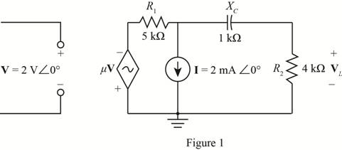
Chapter 19, Problem 10P
Using superposition, for the network of Fig. 19.114, detemine the voltage VL
Expert Solution & Answer
Want to see the full answer?
Check out a sample textbook solution
Students have asked these similar questions
Using superposition, how can I determine the voltage across the capacitor C2 for the network of Fig. 19. 108.
Using supeerposition, determine the current through the inductance XL for the network of Fig. 19.105.
E,= 30 VZ 30°
392
X₁₂
ele
8 Ω
Figure 1
Xc
6Ω
+
E = 60 VZ 10⁰
(a) A voltmeter and an ammeter can be connected as shown in Fig. 19-83a to measure a
resistance R. If V is the voltmeter reading, and / is the ammeter reading, the value of R will not
quite be VI (as in Ohn's law) because some current goes through the voltmeter. Show that the
actual value of Ris
1
I
1
-
R
V
Ry
Where Ry is the voltrneter resistance. Note that R z V/I if Ry > R. (b) A voltmeter
and an ammeter can also be connected as shown in Fig. 19-83b to measure a resistance R.
Show in this case that
V
R
RA,
I
where Vand / are the voltmeter and ammeter readings and Ra is the resistance of the
arnmeter. Note that R = V/I if RA « R.
V
A
A
R
R
(a)
(b)
Chapter 19 Solutions
Introductory Circuit Analysis (13th Edition)
Ch. 19 - Using supeerposition, determine the current...Ch. 19 - Using superposition, determine the current through...Ch. 19 - Using superposition, determine the current IL for...Ch. 19 - Using superposition, determine the voltage across...Ch. 19 - Using superposition, determine the current through...Ch. 19 - Using superposition, find the sinusoidal...Ch. 19 - Using superposition, find the sinusoidal...Ch. 19 - Using superspostion, find the current I for the...Ch. 19 - Using superposition, determine the current IL...Ch. 19 - Using superposition, for the network of Fig....
Ch. 19 - Using superposition, determine the current IL for...Ch. 19 - Determine VL for the network of Fig. 19.116...Ch. 19 - Calculate the current I for the network of Fig....Ch. 19 - Find the voltage Vs for the network in Fig....Ch. 19 - Find the ThĂ©venin equivalent circuit for the...Ch. 19 - Find the Thevenin equivalent circuit for the...Ch. 19 - Find the Thevenin equivalent circuit for the...Ch. 19 - Find the Thevenin equivalent circuit for the...Ch. 19 - Find the Thevenin equivalent circuit for the...Ch. 19 - Find the Thevenin equivalent circuit for the...Ch. 19 - Find the ThĂªvenin equivalent circuit for the...Ch. 19 - Find the ThĂªvenin equivalent circuit for the...Ch. 19 - a. Find the ThĂ©venin equivalent circuit for the...Ch. 19 - a. Find the ThĂ©venin equivalent circuit for the...Ch. 19 - a. Find the ThĂ©venin equivalent circuit of the...Ch. 19 - Determine the ThĂ©venin equivalent circuit for the...Ch. 19 - Determine the ThĂ©venin equivalent circuit for the...Ch. 19 - Prob. 28PCh. 19 - Prob. 29PCh. 19 - Find the ThĂ©venin equivalent circuit for the...Ch. 19 - Determine the ThĂ©venin equivalent circuit for the...Ch. 19 - Prob. 32PCh. 19 - Find the ThĂ©venin equivalent circuit for the...Ch. 19 - Find the Norton equivalent circuit for the network...Ch. 19 - Find the Norton equivalent circuit for the network...Ch. 19 - Find the Norton equivalent circuit for the network...Ch. 19 - Find the Norton equivalent circuit for the portion...Ch. 19 - Find the Norton equivalent circuit for the portion...Ch. 19 - a. Find the Norton equivalent circuit for the...Ch. 19 - a. Find the Norton equivalent circuit for the...Ch. 19 - a. Find the Norton equivalent circuit for the...Ch. 19 - Determine the Norton equivalent circuit for the...Ch. 19 - Determine the Norton equivalent circuit for the...Ch. 19 - Find the Norton equivalent circuit for the network...Ch. 19 - Find the Norton equivalent circuit for the network...Ch. 19 - Prob. 46PCh. 19 - Prob. 47PCh. 19 - Find the load impedance ZL for the network of Fig....Ch. 19 - Find the load impedance ZL for the network of Fig....Ch. 19 - Find the load impedance ZL for the network of Fig....Ch. 19 - Find the load impedance ZL for the network of Fig....Ch. 19 - Prob. 52PCh. 19 - a. Determine the load impedance to replace the...Ch. 19 - a. Determine the load impedance to replace the...Ch. 19 - a. Determine the load impedance to replace the...Ch. 19 - Prob. 56PCh. 19 - a. For the network in Fig. 19.139, determine the...Ch. 19 - For the network in Fig. 19.140, determine two...Ch. 19 - Prob. 59PCh. 19 - Using Millmans theorem, determine the current...Ch. 19 - Prob. 61PCh. 19 - Determine the current IL for the network in Fig....Ch. 19 - Using schematics, determine V2 for the network in...Ch. 19 - Prob. 64PCh. 19 - Using schematics, plot the power to the R-C load...
Knowledge Booster


Learn more about
Need a deep-dive on the concept behind this application? Look no further. Learn more about this topic, electrical-engineering and related others by exploring similar questions and additional content below.Similar questions
- (1I) Determine the magnitudes and directions of the currents through R, and R, in Fig. 19 R1 R2 59. V=9.0 V R=220 R2= 18 2 V3=6.0 V FIGURE 19-59arrow_forward90. Determine the current in each resistor of the circuit shown in Fig. 19–88. 6.00 V ww- 5.00 Ω 12.00 V 6.00 NŽ 12,00 4.00 V FIGURE 19-88 ww Problem 90. 5.00 V 6.80 2arrow_forwardCalculate the current in the circuit of Fig. 19-43 and show that the sum of all the voltage changes around the circuit is zero. 8.0 92 r = 2.0 9 9.0 V 12.0Q2arrow_forward
- 3. For the system given below a. Find the OLTFarrow_forward84. (a) What is the equivalent resistance of the circuit shown in Fig. 19–82? [Hint: Redraw the circuit to see series and parallel better.] (b) What is the current in the 14-0 resis- tor? (c) What is the current in the 12-N resistor? (d) What is the power dissipation in the 4.5-2 resistor? 6.0 V 12 Ω 22 2 14 2 FIGURE 19-82 ww 4.5 Ω Problem 84. wwarrow_forward2. HMA A 552 150 1052 Obtain the single delta equivalent with respect to terminals A, B and C.arrow_forward
- Which of the following is a CDMA standard of second generation network? a) IS-95 b) IS-136 C ) ΕTACS d) EDGEarrow_forwarda. For the network below, determine IB, Ic, VE and VCE o+18 V 9.1 kQ I ka 510 ka YA=130 510 ka 7.5 ka -18 Varrow_forward(II) (a) What is the potential difference between points a and d in Fig. 19–57 (similar to Fig. 19–13, Example 19–8), and (b) what is the terminal voltage of each battery? 34 Ω h r = E2= %3D 47 Ω I3 1Ω 45V a b = 13 85 V 12 r = 18 Ω FIGURE 19-57 Problem 29. g f earrow_forward
- Consider the circuit, here, which are the following options correctly represents f(x, y, z) MUX x' Y y S MUX Y f 1 S y' (A) x'y' +xy + xz (B) xy' +x'y +xz (C) x'y+xy' +y'z (D) xy +x'y' + xyz хуarrow_forwardFor the common-base network, determine the following: (a) Rc (b) IB (c) IE (d) VBC (e) VCE 14 V Vc=8V 4 Vo Rc RE H V₂ B=90 HoVi HH *1.1 ΚΩarrow_forwardObtain the y parameters for the network in Figure below. 2 mH 10nF ll 5Ω ee ll 10 mH 3 2 12 2arrow_forward
arrow_back_ios
SEE MORE QUESTIONS
arrow_forward_ios
Recommended textbooks for you
 Introductory Circuit Analysis (13th Edition)Electrical EngineeringISBN:9780133923605Author:Robert L. BoylestadPublisher:PEARSON
 Delmar's Standard Textbook Of ElectricityElectrical EngineeringISBN:9781337900348Author:Stephen L. HermanPublisher:Cengage Learning
 Programmable Logic ControllersElectrical EngineeringISBN:9780073373843Author:Frank D. PetruzellaPublisher:McGraw-Hill Education
 Fundamentals of Electric CircuitsElectrical EngineeringISBN:9780078028229Author:Charles K Alexander, Matthew SadikuPublisher:McGraw-Hill Education
 Electric Circuits. (11th Edition)Electrical EngineeringISBN:9780134746968Author:James W. Nilsson, Susan RiedelPublisher:PEARSON
 Engineering ElectromagneticsElectrical EngineeringISBN:9780078028151Author:Hayt, William H. (william Hart), Jr, BUCK, John A.Publisher:Mcgraw-hill Education,
Introductory Circuit Analysis (13th Edition)
Electrical Engineering
ISBN:9780133923605
Author:Robert L. Boylestad
Publisher:PEARSON
Delmar's Standard Textbook Of Electricity
Electrical Engineering
ISBN:9781337900348
Author:Stephen L. Herman
Publisher:Cengage Learning
Programmable Logic Controllers
Electrical Engineering
ISBN:9780073373843
Author:Frank D. Petruzella
Publisher:McGraw-Hill Education
Fundamentals of Electric Circuits
Electrical Engineering
ISBN:9780078028229
Author:Charles K Alexander, Matthew Sadiku
Publisher:McGraw-Hill Education
Electric Circuits. (11th Edition)
Electrical Engineering
ISBN:9780134746968
Author:James W. Nilsson, Susan Riedel
Publisher:PEARSON
Engineering Electromagnetics
Electrical Engineering
ISBN:9780078028151
Author:Hayt, William H. (william Hart), Jr, BUCK, John A.
Publisher:Mcgraw-hill Education,
Lecture 4b -- Transmission Line Parameters; Author: EMPossible;https://www.youtube.com/watch?v=naG572ZnXqw;License: Standard Youtube License