
Introductory Circuit Analysis (13th Edition)
13th Edition
ISBN: 9780133923605
Author: Robert L. Boylestad
Publisher: PEARSON
expand_more
expand_more
format_list_bulleted
Videos
Textbook Question
Chapter 19, Problem 21P
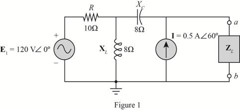
Find the ThĂªvenin equivalent circuit for the portion of the networks of Fig. 19.125 external to the elements between points a and b.
Expert Solution & Answer
Want to see the full answer?
Check out a sample textbook solution
Students have asked these similar questions
Obtain h parameter of the network
*14. For the circuit of Fig. 19.51:
a. Find the total number of watts, volt-amperes reactive,
and volt-amperes, and F.
b. Find the current I..
c. Find the type of elements and their impedance in each
box. (Assume that the elements within each box are in
series.)
Load 2
30 W
40 VAR (L)
Load 1
Load 3
E = 100 V 20 (2)
200 W
Fp = 1
FIG. 19.51
100 VAR (L)
Fp = 0
E = 50 V 260°
Load 1
Load 2
5. For the system of Fig. 19.44:
a. Find PT. Qr, and St.
b. Find the power factor F-
c. Draw the power triangle.
d. Find I,.
Load 4
200 VAR (C)
100 W
100 VAR (Z)
200 W
100 VAR (L)
200 W
Load 3
200 VAR (C)
OW
Chapter 19 Solutions
Introductory Circuit Analysis (13th Edition)
Ch. 19 - Using supeerposition, determine the current...Ch. 19 - Using superposition, determine the current through...Ch. 19 - Using superposition, determine the current IL for...Ch. 19 - Using superposition, determine the voltage across...Ch. 19 - Using superposition, determine the current through...Ch. 19 - Using superposition, find the sinusoidal...Ch. 19 - Using superposition, find the sinusoidal...Ch. 19 - Using superspostion, find the current I for the...Ch. 19 - Using superposition, determine the current IL...Ch. 19 - Using superposition, for the network of Fig....
Ch. 19 - Using superposition, determine the current IL for...Ch. 19 - Determine VL for the network of Fig. 19.116...Ch. 19 - Calculate the current I for the network of Fig....Ch. 19 - Find the voltage Vs for the network in Fig....Ch. 19 - Find the ThĂ©venin equivalent circuit for the...Ch. 19 - Find the Thevenin equivalent circuit for the...Ch. 19 - Find the Thevenin equivalent circuit for the...Ch. 19 - Find the Thevenin equivalent circuit for the...Ch. 19 - Find the Thevenin equivalent circuit for the...Ch. 19 - Find the Thevenin equivalent circuit for the...Ch. 19 - Find the ThĂªvenin equivalent circuit for the...Ch. 19 - Find the ThĂªvenin equivalent circuit for the...Ch. 19 - a. Find the ThĂ©venin equivalent circuit for the...Ch. 19 - a. Find the ThĂ©venin equivalent circuit for the...Ch. 19 - a. Find the ThĂ©venin equivalent circuit of the...Ch. 19 - Determine the ThĂ©venin equivalent circuit for the...Ch. 19 - Determine the ThĂ©venin equivalent circuit for the...Ch. 19 - Prob. 28PCh. 19 - Prob. 29PCh. 19 - Find the ThĂ©venin equivalent circuit for the...Ch. 19 - Determine the ThĂ©venin equivalent circuit for the...Ch. 19 - Prob. 32PCh. 19 - Find the ThĂ©venin equivalent circuit for the...Ch. 19 - Find the Norton equivalent circuit for the network...Ch. 19 - Find the Norton equivalent circuit for the network...Ch. 19 - Find the Norton equivalent circuit for the network...Ch. 19 - Find the Norton equivalent circuit for the portion...Ch. 19 - Find the Norton equivalent circuit for the portion...Ch. 19 - a. Find the Norton equivalent circuit for the...Ch. 19 - a. Find the Norton equivalent circuit for the...Ch. 19 - a. Find the Norton equivalent circuit for the...Ch. 19 - Determine the Norton equivalent circuit for the...Ch. 19 - Determine the Norton equivalent circuit for the...Ch. 19 - Find the Norton equivalent circuit for the network...Ch. 19 - Find the Norton equivalent circuit for the network...Ch. 19 - Prob. 46PCh. 19 - Prob. 47PCh. 19 - Find the load impedance ZL for the network of Fig....Ch. 19 - Find the load impedance ZL for the network of Fig....Ch. 19 - Find the load impedance ZL for the network of Fig....Ch. 19 - Find the load impedance ZL for the network of Fig....Ch. 19 - Prob. 52PCh. 19 - a. Determine the load impedance to replace the...Ch. 19 - a. Determine the load impedance to replace the...Ch. 19 - a. Determine the load impedance to replace the...Ch. 19 - Prob. 56PCh. 19 - a. For the network in Fig. 19.139, determine the...Ch. 19 - For the network in Fig. 19.140, determine two...Ch. 19 - Prob. 59PCh. 19 - Using Millmans theorem, determine the current...Ch. 19 - Prob. 61PCh. 19 - Determine the current IL for the network in Fig....Ch. 19 - Using schematics, determine V2 for the network in...Ch. 19 - Prob. 64PCh. 19 - Using schematics, plot the power to the R-C load...
Knowledge Booster


Learn more about
Need a deep-dive on the concept behind this application? Look no further. Learn more about this topic, electrical-engineering and related others by exploring similar questions and additional content below.Similar questions
- *14. For the circuit of Fig. 19.51: a. Find the total number of watts, volt-amperes reactive, and volt-amperes, and Fp. b. Find the current I.. c. Find the type of elements and their impedance in each box. (Assume that the elements within each box are in series.) Load 2 30 W 40 VAR (Z) Load 1 Load 3 E = 100 V 20° 200 W F₂ = 1 FIG. 19.51 100 VAR (L) F₂ = 0arrow_forwardUsing superposition, how can I determine the voltage across the capacitor C2 for the network of Fig. 19. 108.arrow_forwardet- me 17. Determine the driving point impedence of the network in Fig. P. 12.17 as seen from terminal 11' given that N₁ and N₂ are iden- tical. Each of the two parts is characterised by 10- 1'0- Zoc= [21] 1 1 schola N₁₁ 5Ω www N₂ Fig. P. 12.17 2018 www 1 Ωarrow_forward
- E = 50 V 260° Load 1 Load 2 5. For the system of Fig. 19.44: a. Find Pr. Qr, and ST. b. Find the power factor Fp. c. Draw the power triangle. d. Find I.. Load 4 200 VAR (C) 100 W 100 VAR (L) 200 W 100 VAR (L) 200 W FIG. 19.44 Load 3 200 VAR (C) OWarrow_forwardConsider a bipartite network, with its two types of nodes, and suppose that there are n1 nodes of type 1 and n2 nodes of type 2. Show that the mean degrees c1 and c2 of the two types are related by c2= (n1/n2) * c1arrow_forwardDetermine the following for the network shown below: a. b ZiAMP C. ZOAMP d. Given parameters: R1 = 20 ΜΩ R2 = 5 ΜΩ RD = 3.3 kΩ Rs = 2 kΩ Rsig = 1000 2 R = 1.5 ΚΩ VDD = 22 V AVAMP Rig 5+ IDss = 9 mA VP = -6 V yos = 25 μµS C₁ = 0.02 μF C₂ = 1 μF Cs = 2.2 µF J1 RS 0+ VDD w Aarrow_forward
- Determine the following for the network shown below: a. b. ZiAMP c. ZOAMP d. Given parameters: R, = 20 ΜΩ R2 = 5 ΜΩ RD = 3.3 ΚΩ Rs = 2 ΚΩ Rsig = 1000 2 Rt = 1.5 ΚΩ VDD = 22 V AVAMP Rig 中口 în Ipss = 9 mA VP=-6 V yos = 25 μS C₁ = 0.02 µF C₂ = 1 μF Cs=2.2 µF B₁ VDOarrow_forward10. A circuit consists of a pure resistance and a coil in series. The power dissipated in the resistance is 500 W and the drop across it is 100 V. The power dissipated in the coil is 100 W and the drop across it is 50 V. Find the reactance and resistance of the coil and the supply voltage. 19.1682 40 128.5V]arrow_forwardFind the Thévenin equivalent circuit for the portion of the network of Fig. 19.119 external to the elements between points a and b. R 3Ω E = 100 V Z0° | XL FIG. 19.119arrow_forward
- (a) A voltmeter and an ammeter can be connected as shown in Fig. 19-83a to measure a resistance R. If V is the voltmeter reading, and / is the ammeter reading, the value of R will not quite be VI (as in Ohn's law) because some current goes through the voltmeter. Show that the actual value of Ris 1 I 1 - R V Ry Where Ry is the voltrneter resistance. Note that R z V/I if Ry > R. (b) A voltmeter and an ammeter can also be connected as shown in Fig. 19-83b to measure a resistance R. Show in this case that V R RA, I where Vand / are the voltmeter and ammeter readings and Ra is the resistance of the arnmeter. Note that R = V/I if RA « R. V A A R R (a) (b)arrow_forwardDetermine the Vo and ID for the networks below: COMPLETE SOLUTIONarrow_forwardFind the Y-parameters for the network shown. Determine whether the network is symmetrical or reciprocal. エ2 0:52 V2arrow_forward
arrow_back_ios
SEE MORE QUESTIONS
arrow_forward_ios
Recommended textbooks for you
 Introductory Circuit Analysis (13th Edition)Electrical EngineeringISBN:9780133923605Author:Robert L. BoylestadPublisher:PEARSON
 Delmar's Standard Textbook Of ElectricityElectrical EngineeringISBN:9781337900348Author:Stephen L. HermanPublisher:Cengage Learning
 Programmable Logic ControllersElectrical EngineeringISBN:9780073373843Author:Frank D. PetruzellaPublisher:McGraw-Hill Education
 Fundamentals of Electric CircuitsElectrical EngineeringISBN:9780078028229Author:Charles K Alexander, Matthew SadikuPublisher:McGraw-Hill Education
 Electric Circuits. (11th Edition)Electrical EngineeringISBN:9780134746968Author:James W. Nilsson, Susan RiedelPublisher:PEARSON
 Engineering ElectromagneticsElectrical EngineeringISBN:9780078028151Author:Hayt, William H. (william Hart), Jr, BUCK, John A.Publisher:Mcgraw-hill Education,
Introductory Circuit Analysis (13th Edition)
Electrical Engineering
ISBN:9780133923605
Author:Robert L. Boylestad
Publisher:PEARSON
Delmar's Standard Textbook Of Electricity
Electrical Engineering
ISBN:9781337900348
Author:Stephen L. Herman
Publisher:Cengage Learning
Programmable Logic Controllers
Electrical Engineering
ISBN:9780073373843
Author:Frank D. Petruzella
Publisher:McGraw-Hill Education
Fundamentals of Electric Circuits
Electrical Engineering
ISBN:9780078028229
Author:Charles K Alexander, Matthew Sadiku
Publisher:McGraw-Hill Education
Electric Circuits. (11th Edition)
Electrical Engineering
ISBN:9780134746968
Author:James W. Nilsson, Susan Riedel
Publisher:PEARSON
Engineering Electromagnetics
Electrical Engineering
ISBN:9780078028151
Author:Hayt, William H. (william Hart), Jr, BUCK, John A.
Publisher:Mcgraw-hill Education,
Introduction to Two-Port Networks; Author: ALL ABOUT ELECTRONICS;https://www.youtube.com/watch?v=ru2ItcD6unI;License: Standard Youtube License