
Introductory Circuit Analysis (13th Edition)
13th Edition
ISBN: 9780133923605
Author: Robert L. Boylestad
Publisher: PEARSON
expand_more
expand_more
format_list_bulleted
Videos
Textbook Question
Chapter 19, Problem 60P
Using Millman’s theorem, determine the current through the 4 k
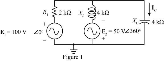
Fig. 19.142
Expert Solution & Answer
Want to see the full answer?
Check out a sample textbook solution
Students have asked these similar questions
Using superposition, how can I determine the voltage across the capacitor C2 for the network of Fig. 19. 108.
Find Z and Y parameters of the following network if they exist:
2₁
'b
Za
1:n
000
Ideal
10. A circuit consists of a pure resistance and a coil in series. The power dissipated in the resistance is
500 W and the drop across it is 100 V. The power dissipated in the coil is 100 W and the drop across
it is 50 V. Find the reactance and resistance of the coil and the supply voltage.
19.1682 40 128.5V]
Chapter 19 Solutions
Introductory Circuit Analysis (13th Edition)
Ch. 19 - Using supeerposition, determine the current...Ch. 19 - Using superposition, determine the current through...Ch. 19 - Using superposition, determine the current IL for...Ch. 19 - Using superposition, determine the voltage across...Ch. 19 - Using superposition, determine the current through...Ch. 19 - Using superposition, find the sinusoidal...Ch. 19 - Using superposition, find the sinusoidal...Ch. 19 - Using superspostion, find the current I for the...Ch. 19 - Using superposition, determine the current IL...Ch. 19 - Using superposition, for the network of Fig....
Ch. 19 - Using superposition, determine the current IL for...Ch. 19 - Determine VL for the network of Fig. 19.116...Ch. 19 - Calculate the current I for the network of Fig....Ch. 19 - Find the voltage Vs for the network in Fig....Ch. 19 - Find the ThĂ©venin equivalent circuit for the...Ch. 19 - Find the Thevenin equivalent circuit for the...Ch. 19 - Find the Thevenin equivalent circuit for the...Ch. 19 - Find the Thevenin equivalent circuit for the...Ch. 19 - Find the Thevenin equivalent circuit for the...Ch. 19 - Find the Thevenin equivalent circuit for the...Ch. 19 - Find the ThĂªvenin equivalent circuit for the...Ch. 19 - Find the ThĂªvenin equivalent circuit for the...Ch. 19 - a. Find the ThĂ©venin equivalent circuit for the...Ch. 19 - a. Find the ThĂ©venin equivalent circuit for the...Ch. 19 - a. Find the ThĂ©venin equivalent circuit of the...Ch. 19 - Determine the ThĂ©venin equivalent circuit for the...Ch. 19 - Determine the ThĂ©venin equivalent circuit for the...Ch. 19 - Prob. 28PCh. 19 - Prob. 29PCh. 19 - Find the ThĂ©venin equivalent circuit for the...Ch. 19 - Determine the ThĂ©venin equivalent circuit for the...Ch. 19 - Prob. 32PCh. 19 - Find the ThĂ©venin equivalent circuit for the...Ch. 19 - Find the Norton equivalent circuit for the network...Ch. 19 - Find the Norton equivalent circuit for the network...Ch. 19 - Find the Norton equivalent circuit for the network...Ch. 19 - Find the Norton equivalent circuit for the portion...Ch. 19 - Find the Norton equivalent circuit for the portion...Ch. 19 - a. Find the Norton equivalent circuit for the...Ch. 19 - a. Find the Norton equivalent circuit for the...Ch. 19 - a. Find the Norton equivalent circuit for the...Ch. 19 - Determine the Norton equivalent circuit for the...Ch. 19 - Determine the Norton equivalent circuit for the...Ch. 19 - Find the Norton equivalent circuit for the network...Ch. 19 - Find the Norton equivalent circuit for the network...Ch. 19 - Prob. 46PCh. 19 - Prob. 47PCh. 19 - Find the load impedance ZL for the network of Fig....Ch. 19 - Find the load impedance ZL for the network of Fig....Ch. 19 - Find the load impedance ZL for the network of Fig....Ch. 19 - Find the load impedance ZL for the network of Fig....Ch. 19 - Prob. 52PCh. 19 - a. Determine the load impedance to replace the...Ch. 19 - a. Determine the load impedance to replace the...Ch. 19 - a. Determine the load impedance to replace the...Ch. 19 - Prob. 56PCh. 19 - a. For the network in Fig. 19.139, determine the...Ch. 19 - For the network in Fig. 19.140, determine two...Ch. 19 - Prob. 59PCh. 19 - Using Millmans theorem, determine the current...Ch. 19 - Prob. 61PCh. 19 - Determine the current IL for the network in Fig....Ch. 19 - Using schematics, determine V2 for the network in...Ch. 19 - Prob. 64PCh. 19 - Using schematics, plot the power to the R-C load...
Knowledge Booster


Learn more about
Need a deep-dive on the concept behind this application? Look no further. Learn more about this topic, electrical-engineering and related others by exploring similar questions and additional content below.Similar questions
- *14. For the circuit of Fig. 19.51: a. Find the total number of watts, volt-amperes reactive, and volt-amperes, and F. b. Find the current I.. c. Find the type of elements and their impedance in each box. (Assume that the elements within each box are in series.) Load 2 30 W 40 VAR (L) Load 1 Load 3 E = 100 V 20 (2) 200 W Fp = 1 FIG. 19.51 100 VAR (L) Fp = 0arrow_forward(a) A voltmeter and an ammeter can be connected as shown in Fig. 19-83a to measure a resistance R. If V is the voltmeter reading, and / is the ammeter reading, the value of R will not quite be VI (as in Ohn's law) because some current goes through the voltmeter. Show that the actual value of Ris 1 I 1 - R V Ry Where Ry is the voltrneter resistance. Note that R z V/I if Ry > R. (b) A voltmeter and an ammeter can also be connected as shown in Fig. 19-83b to measure a resistance R. Show in this case that V R RA, I where Vand / are the voltmeter and ammeter readings and Ra is the resistance of the arnmeter. Note that R = V/I if RA « R. V A A R R (a) (b)arrow_forwardDetermine the following for the network shown below: a. b ZiAMP C. ZOAMP d. Given parameters: R1 = 20 ΜΩ R2 = 5 ΜΩ RD = 3.3 kΩ Rs = 2 kΩ Rsig = 1000 2 R = 1.5 ΚΩ VDD = 22 V AVAMP Rig 5+ IDss = 9 mA VP = -6 V yos = 25 μµS C₁ = 0.02 μF C₂ = 1 μF Cs = 2.2 µF J1 RS 0+ VDD w Aarrow_forward
- *14. For the circuit of Fig. 19.51: a. Find the total number of watts, volt-amperes reactive, and volt-amperes, and Fp. b. Find the current I.. c. Find the type of elements and their impedance in each box. (Assume that the elements within each box are in series.) Load 2 30 W 40 VAR (Z) Load 1 Load 3 E = 100 V 20° 200 W F₂ = 1 FIG. 19.51 100 VAR (L) F₂ = 0arrow_forwards/۸,۱ 2 30 1[ ۳۸ ١:٥٢ م 4.jpg → *14. For the circuit of Fig. 19.51: a. Find the total number of watts, volt-amperes reactive, and volt-amperes, and Fp- b. Find the current I.. c. Find the type of elements and their impedance in each box. (Assume that the elements within each box are in series.) Load 2 30 W 40 VAR (L) L Load 1 Load 3 ... E = 100 V 20° O 200 W Fp = 1 FIG. 19.51 100 VAR (Z) = 0arrow_forward19:48 ◄ Messages Health and Safety Mr Ali Lilo, AL4510222L Time remaining: 54 Quick Questainfonds Select of Health and Safety at Work published by the HSE and is aimed at a) sub- contractors b) people who are managing a business c) employees d) apprentices 5G 15 Prev Next 17 Questi 18 Questi 19 Questi 20 Questi 21 Questi 22 Questi Submit Answersarrow_forward
- PROBLEM 1. 60 W For the battery of bulbs (purely resistive) appearing in Fig. 19.40: a. Determine the total power dissipation. b. Calculate the total reactive and apparent power. c. Find the source current I,. d. Calculate the resistance of each bulb for the specified operating conditions. e. Detemine the curents I, and Iz. E ( ) 240 V 20 W 40 W FIG. 19.40 SOLUTIONarrow_forwardFind the Norton equivalent of the curcuitarrow_forwardE = 50 V 260° Load 1 Load 2 5. For the system of Fig. 19.44: a. Find PT. Qr, and St. b. Find the power factor F- c. Draw the power triangle. d. Find I,. Load 4 200 VAR (C) 100 W 100 VAR (Z) 200 W 100 VAR (L) 200 W Load 3 200 VAR (C) OWarrow_forward
- 19:50 ◄ Messages Health and Safety Mr Ali Lilo, AL4510222L Time remaining: 52 Quick QuestiBits seconds Select method for reducing the effects of excessive noise is to a) ensure the noise has been assessed correctly and the required limits applied correctly b) provide hearing protection c) apply sound insulation to the noise source d) reduce the noise level by 10 dB 5G (14 Prev Next 26 Questi 27 Questi 28 Questi 29 Questi 30 Questi 31 Questi 32 Submit Answersarrow_forward(II) Determine the magnitudes and directions of the currents in each resistor shown in Fig. 19–56. The batteries have emfs of & = 9.0 V and & = 12.0 V and the resistors have values of R¡ = 25 N, R, = 68 N, and R3 = 35 N. (a) Ignore internal resistance of the batteries. (b) Assume each battery has internal resistance ©1 r = 1.0 2. R1 ww R2 ww R3 FIGURE 19–56 Problem 28.arrow_forwardObtain h parameter of the networkarrow_forward
arrow_back_ios
SEE MORE QUESTIONS
arrow_forward_ios
Recommended textbooks for you
 Introductory Circuit Analysis (13th Edition)Electrical EngineeringISBN:9780133923605Author:Robert L. BoylestadPublisher:PEARSON
 Delmar's Standard Textbook Of ElectricityElectrical EngineeringISBN:9781337900348Author:Stephen L. HermanPublisher:Cengage Learning
 Programmable Logic ControllersElectrical EngineeringISBN:9780073373843Author:Frank D. PetruzellaPublisher:McGraw-Hill Education
 Fundamentals of Electric CircuitsElectrical EngineeringISBN:9780078028229Author:Charles K Alexander, Matthew SadikuPublisher:McGraw-Hill Education
 Electric Circuits. (11th Edition)Electrical EngineeringISBN:9780134746968Author:James W. Nilsson, Susan RiedelPublisher:PEARSON
 Engineering ElectromagneticsElectrical EngineeringISBN:9780078028151Author:Hayt, William H. (william Hart), Jr, BUCK, John A.Publisher:Mcgraw-hill Education,
Introductory Circuit Analysis (13th Edition)
Electrical Engineering
ISBN:9780133923605
Author:Robert L. Boylestad
Publisher:PEARSON
Delmar's Standard Textbook Of Electricity
Electrical Engineering
ISBN:9781337900348
Author:Stephen L. Herman
Publisher:Cengage Learning
Programmable Logic Controllers
Electrical Engineering
ISBN:9780073373843
Author:Frank D. Petruzella
Publisher:McGraw-Hill Education
Fundamentals of Electric Circuits
Electrical Engineering
ISBN:9780078028229
Author:Charles K Alexander, Matthew Sadiku
Publisher:McGraw-Hill Education
Electric Circuits. (11th Edition)
Electrical Engineering
ISBN:9780134746968
Author:James W. Nilsson, Susan Riedel
Publisher:PEARSON
Engineering Electromagnetics
Electrical Engineering
ISBN:9780078028151
Author:Hayt, William H. (william Hart), Jr, BUCK, John A.
Publisher:Mcgraw-hill Education,
Inductors Explained - The basics how inductors work working principle; Author: The Engineering Mindset;https://www.youtube.com/watch?v=KSylo01n5FY;License: Standard Youtube License