
Introductory Circuit Analysis (13th Edition)
13th Edition
ISBN: 9780133923605
Author: Robert L. Boylestad
Publisher: PEARSON
expand_more
expand_more
format_list_bulleted
Videos
Textbook Question
Chapter 19, Problem 50P
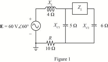
Find the load impedance ZL for the network of Fig. 19.135 for maximum power to the load, and find the maximum power to the load.
Expert Solution & Answer
Want to see the full answer?
Check out a sample textbook solution
Students have asked these similar questions
E = 50 V 260°
Load 1
Load 2
5. For the system of Fig. 19.44:
a. Find PT. Qr, and St.
b. Find the power factor F-
c. Draw the power triangle.
d. Find I,.
Load 4
200 VAR (C)
100 W
100 VAR (Z)
200 W
100 VAR (L)
200 W
Load 3
200 VAR (C)
OW
10. A circuit consists of a pure resistance and a coil in series. The power dissipated in the resistance is
500 W and the drop across it is 100 V. The power dissipated in the coil is 100 W and the drop across
it is 50 V. Find the reactance and resistance of the coil and the supply voltage.
19.1682 40 128.5V]
QI find the Value of c so that the
network impedance is Resistive at
a hequ encyof
2KHZ
Chapter 19 Solutions
Introductory Circuit Analysis (13th Edition)
Ch. 19 - Using supeerposition, determine the current...Ch. 19 - Using superposition, determine the current through...Ch. 19 - Using superposition, determine the current IL for...Ch. 19 - Using superposition, determine the voltage across...Ch. 19 - Using superposition, determine the current through...Ch. 19 - Using superposition, find the sinusoidal...Ch. 19 - Using superposition, find the sinusoidal...Ch. 19 - Using superspostion, find the current I for the...Ch. 19 - Using superposition, determine the current IL...Ch. 19 - Using superposition, for the network of Fig....
Ch. 19 - Using superposition, determine the current IL for...Ch. 19 - Determine VL for the network of Fig. 19.116...Ch. 19 - Calculate the current I for the network of Fig....Ch. 19 - Find the voltage Vs for the network in Fig....Ch. 19 - Find the ThĂ©venin equivalent circuit for the...Ch. 19 - Find the Thevenin equivalent circuit for the...Ch. 19 - Find the Thevenin equivalent circuit for the...Ch. 19 - Find the Thevenin equivalent circuit for the...Ch. 19 - Find the Thevenin equivalent circuit for the...Ch. 19 - Find the Thevenin equivalent circuit for the...Ch. 19 - Find the ThĂªvenin equivalent circuit for the...Ch. 19 - Find the ThĂªvenin equivalent circuit for the...Ch. 19 - a. Find the ThĂ©venin equivalent circuit for the...Ch. 19 - a. Find the ThĂ©venin equivalent circuit for the...Ch. 19 - a. Find the ThĂ©venin equivalent circuit of the...Ch. 19 - Determine the ThĂ©venin equivalent circuit for the...Ch. 19 - Determine the ThĂ©venin equivalent circuit for the...Ch. 19 - Prob. 28PCh. 19 - Prob. 29PCh. 19 - Find the ThĂ©venin equivalent circuit for the...Ch. 19 - Determine the ThĂ©venin equivalent circuit for the...Ch. 19 - Prob. 32PCh. 19 - Find the ThĂ©venin equivalent circuit for the...Ch. 19 - Find the Norton equivalent circuit for the network...Ch. 19 - Find the Norton equivalent circuit for the network...Ch. 19 - Find the Norton equivalent circuit for the network...Ch. 19 - Find the Norton equivalent circuit for the portion...Ch. 19 - Find the Norton equivalent circuit for the portion...Ch. 19 - a. Find the Norton equivalent circuit for the...Ch. 19 - a. Find the Norton equivalent circuit for the...Ch. 19 - a. Find the Norton equivalent circuit for the...Ch. 19 - Determine the Norton equivalent circuit for the...Ch. 19 - Determine the Norton equivalent circuit for the...Ch. 19 - Find the Norton equivalent circuit for the network...Ch. 19 - Find the Norton equivalent circuit for the network...Ch. 19 - Prob. 46PCh. 19 - Prob. 47PCh. 19 - Find the load impedance ZL for the network of Fig....Ch. 19 - Find the load impedance ZL for the network of Fig....Ch. 19 - Find the load impedance ZL for the network of Fig....Ch. 19 - Find the load impedance ZL for the network of Fig....Ch. 19 - Prob. 52PCh. 19 - a. Determine the load impedance to replace the...Ch. 19 - a. Determine the load impedance to replace the...Ch. 19 - a. Determine the load impedance to replace the...Ch. 19 - Prob. 56PCh. 19 - a. For the network in Fig. 19.139, determine the...Ch. 19 - For the network in Fig. 19.140, determine two...Ch. 19 - Prob. 59PCh. 19 - Using Millmans theorem, determine the current...Ch. 19 - Prob. 61PCh. 19 - Determine the current IL for the network in Fig....Ch. 19 - Using schematics, determine V2 for the network in...Ch. 19 - Prob. 64PCh. 19 - Using schematics, plot the power to the R-C load...
Knowledge Booster


Learn more about
Need a deep-dive on the concept behind this application? Look no further. Learn more about this topic, electrical-engineering and related others by exploring similar questions and additional content below.Similar questions
- Obtain h parameter of the networkarrow_forwardE = 50 V 260° Load 1 Load 2 5. For the system of Fig. 19.44: a. Find Pr. Qr, and ST. b. Find the power factor Fp. c. Draw the power triangle. d. Find I.. Load 4 200 VAR (C) 100 W 100 VAR (L) 200 W 100 VAR (L) 200 W FIG. 19.44 Load 3 200 VAR (C) OWarrow_forwardObtain Hybrid parameter for the networkarrow_forward
- Q. A symmetrical T-network having a series arm resistance of 1000 and shunt arm resistance of 400. Obtain the equivalent n network and calculate its characteristic impedance.arrow_forward*14. For the circuit of Fig. 19.51: a. Find the total number of watts, volt-amperes reactive, and volt-amperes, and Fp. b. Find the current I.. c. Find the type of elements and their impedance in each box. (Assume that the elements within each box are in series.) Load 2 30 W 40 VAR (Z) Load 1 Load 3 E = 100 V 20° 200 W F₂ = 1 FIG. 19.51 100 VAR (L) F₂ = 0arrow_forwardFind the Thevenin’s equivalent circuit for terminal pair AB for the network shownarrow_forward
- *14. For the circuit of Fig. 19.51: a. Find the total number of watts, volt-amperes reactive, and volt-amperes, and F. b. Find the current I.. c. Find the type of elements and their impedance in each box. (Assume that the elements within each box are in series.) Load 2 30 W 40 VAR (L) Load 1 Load 3 E = 100 V 20 (2) 200 W Fp = 1 FIG. 19.51 100 VAR (L) Fp = 0arrow_forward23. Using Thevenin's theorem, determine the current in branch BD of the network shown in Fig. 19. [Bombay Univ. Basic Electricity October 1974] [Ans. 2.7 A from B to D] 802 12 12 108 V Fig. 19 1402arrow_forward*9. For the network of Fig. 19.48: a. Find the average power delivered to each element. b. Find the reactive power for each element. c. Find the apparent power for each element. d. Find the total number of watts, volt-amperes reactive, and volt-amperes, and the power factor F, of the cir- cuit. e. Sketch the power triangle. f. Find the energy dissipated by the resistor over one full cycle of the input voltage. g. Find the energy stored or returned by the capacitor and the inductor over one half-cycle of the power curve for each. L 000 0.1 H E = 50 V 20⁰ 100 μF R300 FIG. 19.48arrow_forward
- 2 port network T-Network attenuator has a R1=25.975ohms and R2=35.136ohms. Calculate the characteristic impedance and attenuation. Grateful help with this thanksarrow_forwardUsing superposition, how can I determine the voltage across the capacitor C2 for the network of Fig. 19. 108.arrow_forwardet- me 17. Determine the driving point impedence of the network in Fig. P. 12.17 as seen from terminal 11' given that N₁ and N₂ are iden- tical. Each of the two parts is characterised by 10- 1'0- Zoc= [21] 1 1 schola N₁₁ 5Ω www N₂ Fig. P. 12.17 2018 www 1 Ωarrow_forward
arrow_back_ios
SEE MORE QUESTIONS
arrow_forward_ios
Recommended textbooks for you
 Introductory Circuit Analysis (13th Edition)Electrical EngineeringISBN:9780133923605Author:Robert L. BoylestadPublisher:PEARSON
 Delmar's Standard Textbook Of ElectricityElectrical EngineeringISBN:9781337900348Author:Stephen L. HermanPublisher:Cengage Learning
 Programmable Logic ControllersElectrical EngineeringISBN:9780073373843Author:Frank D. PetruzellaPublisher:McGraw-Hill Education
 Fundamentals of Electric CircuitsElectrical EngineeringISBN:9780078028229Author:Charles K Alexander, Matthew SadikuPublisher:McGraw-Hill Education
 Electric Circuits. (11th Edition)Electrical EngineeringISBN:9780134746968Author:James W. Nilsson, Susan RiedelPublisher:PEARSON
 Engineering ElectromagneticsElectrical EngineeringISBN:9780078028151Author:Hayt, William H. (william Hart), Jr, BUCK, John A.Publisher:Mcgraw-hill Education,
Introductory Circuit Analysis (13th Edition)
Electrical Engineering
ISBN:9780133923605
Author:Robert L. Boylestad
Publisher:PEARSON
Delmar's Standard Textbook Of Electricity
Electrical Engineering
ISBN:9781337900348
Author:Stephen L. Herman
Publisher:Cengage Learning
Programmable Logic Controllers
Electrical Engineering
ISBN:9780073373843
Author:Frank D. Petruzella
Publisher:McGraw-Hill Education
Fundamentals of Electric Circuits
Electrical Engineering
ISBN:9780078028229
Author:Charles K Alexander, Matthew Sadiku
Publisher:McGraw-Hill Education
Electric Circuits. (11th Edition)
Electrical Engineering
ISBN:9780134746968
Author:James W. Nilsson, Susan Riedel
Publisher:PEARSON
Engineering Electromagnetics
Electrical Engineering
ISBN:9780078028151
Author:Hayt, William H. (william Hart), Jr, BUCK, John A.
Publisher:Mcgraw-hill Education,
Introduction to Two-Port Networks; Author: ALL ABOUT ELECTRONICS;https://www.youtube.com/watch?v=ru2ItcD6unI;License: Standard Youtube License