
Introductory Circuit Analysis (13th Edition)
13th Edition
ISBN: 9780133923605
Author: Robert L. Boylestad
Publisher: PEARSON
expand_more
expand_more
format_list_bulleted
Videos
Textbook Question
Chapter 19, Problem 57P
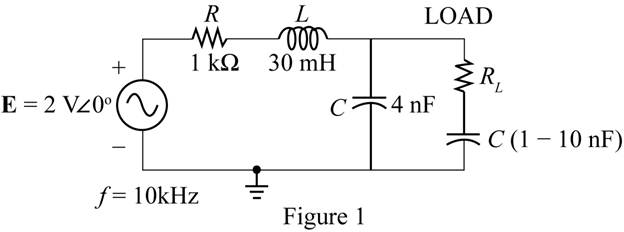
a. For the network in Fig. 19.139, determine the level of capacitance that will ensure maximum power to the load if the range of capacitance is limited to 1 nF to 10 nF.
b. Using the results of part (a), determine the value of RL that will ensure maximum power to the load.
c. Using the results of parts (a) and (b), determine the maximum power to the load.
Expert Solution & Answer
Want to see the full answer?
Check out a sample textbook solution
Students have asked these similar questions
It states that "in any electrical network, the algebraic sum of the currents meeting at a point or junction is zero".
a. kirchoff's current law
b. kircchoff's current law
c. kirchooff's current law
d. kirchhoff's current law
7. A 400-N resistor is connected in series with a 2358 pF capacitor across a 12 V a.c.
supply. Determine the supply frequency if the current flowing in the circuit is 24 mA.
2) From the given digram of inductance comparison bridge circuit, determine the value of Rx and Lx at balance
condition.
R₁
R₂
2
Unknown
inductance
Chapter 19 Solutions
Introductory Circuit Analysis (13th Edition)
Ch. 19 - Using supeerposition, determine the current...Ch. 19 - Using superposition, determine the current through...Ch. 19 - Using superposition, determine the current IL for...Ch. 19 - Using superposition, determine the voltage across...Ch. 19 - Using superposition, determine the current through...Ch. 19 - Using superposition, find the sinusoidal...Ch. 19 - Using superposition, find the sinusoidal...Ch. 19 - Using superspostion, find the current I for the...Ch. 19 - Using superposition, determine the current IL...Ch. 19 - Using superposition, for the network of Fig....
Ch. 19 - Using superposition, determine the current IL for...Ch. 19 - Determine VL for the network of Fig. 19.116...Ch. 19 - Calculate the current I for the network of Fig....Ch. 19 - Find the voltage Vs for the network in Fig....Ch. 19 - Find the ThĂ©venin equivalent circuit for the...Ch. 19 - Find the Thevenin equivalent circuit for the...Ch. 19 - Find the Thevenin equivalent circuit for the...Ch. 19 - Find the Thevenin equivalent circuit for the...Ch. 19 - Find the Thevenin equivalent circuit for the...Ch. 19 - Find the Thevenin equivalent circuit for the...Ch. 19 - Find the ThĂªvenin equivalent circuit for the...Ch. 19 - Find the ThĂªvenin equivalent circuit for the...Ch. 19 - a. Find the ThĂ©venin equivalent circuit for the...Ch. 19 - a. Find the ThĂ©venin equivalent circuit for the...Ch. 19 - a. Find the ThĂ©venin equivalent circuit of the...Ch. 19 - Determine the ThĂ©venin equivalent circuit for the...Ch. 19 - Determine the ThĂ©venin equivalent circuit for the...Ch. 19 - Prob. 28PCh. 19 - Prob. 29PCh. 19 - Find the ThĂ©venin equivalent circuit for the...Ch. 19 - Determine the ThĂ©venin equivalent circuit for the...Ch. 19 - Prob. 32PCh. 19 - Find the ThĂ©venin equivalent circuit for the...Ch. 19 - Find the Norton equivalent circuit for the network...Ch. 19 - Find the Norton equivalent circuit for the network...Ch. 19 - Find the Norton equivalent circuit for the network...Ch. 19 - Find the Norton equivalent circuit for the portion...Ch. 19 - Find the Norton equivalent circuit for the portion...Ch. 19 - a. Find the Norton equivalent circuit for the...Ch. 19 - a. Find the Norton equivalent circuit for the...Ch. 19 - a. Find the Norton equivalent circuit for the...Ch. 19 - Determine the Norton equivalent circuit for the...Ch. 19 - Determine the Norton equivalent circuit for the...Ch. 19 - Find the Norton equivalent circuit for the network...Ch. 19 - Find the Norton equivalent circuit for the network...Ch. 19 - Prob. 46PCh. 19 - Prob. 47PCh. 19 - Find the load impedance ZL for the network of Fig....Ch. 19 - Find the load impedance ZL for the network of Fig....Ch. 19 - Find the load impedance ZL for the network of Fig....Ch. 19 - Find the load impedance ZL for the network of Fig....Ch. 19 - Prob. 52PCh. 19 - a. Determine the load impedance to replace the...Ch. 19 - a. Determine the load impedance to replace the...Ch. 19 - a. Determine the load impedance to replace the...Ch. 19 - Prob. 56PCh. 19 - a. For the network in Fig. 19.139, determine the...Ch. 19 - For the network in Fig. 19.140, determine two...Ch. 19 - Prob. 59PCh. 19 - Using Millmans theorem, determine the current...Ch. 19 - Prob. 61PCh. 19 - Determine the current IL for the network in Fig....Ch. 19 - Using schematics, determine V2 for the network in...Ch. 19 - Prob. 64PCh. 19 - Using schematics, plot the power to the R-C load...
Knowledge Booster


Learn more about
Need a deep-dive on the concept behind this application? Look no further. Learn more about this topic, electrical-engineering and related others by exploring similar questions and additional content below.Similar questions
- For the network of fig a- Find the total capacitance. 6.Determine the charge on each plate. C. Finel the total charge. d. Determine the Energig stored by each capacitor. 40MF 50 HF 20V C 30 UF C2 C3 Q3 1,arrow_forward1:three 12f capacitor are connected in series across 750v supply .calculate A. The equivalent capacitance B.the charge on each capacitor C.the p.d across each capacitor.arrow_forwardfor the circuit shown below If v_in=5 sin2m10t then corner frequency will be ......Hz 1 UF 2 k Ohm 1 k Ohim 050 060 070 080 vinarrow_forward
- Variation of which of the following parameter is not consider as power quality problem for industry?VoltageCurrentPowerFrequencyarrow_forwarda utility company plans to connect a total of 20 uf of capacitance to a 7200 v line at 60 hertz to make this connection the capacitors will be connected in series what is the capacitance of each capacitor what is the minimu ac voltage of each capacitor what is the current flow of the circuit and what is the kvar rating of each capacitor.arrow_forward13. If three 10 uF capacitors are connected in parallel, the net cararitance is A. 20 uF B. 30 UE C. 40 uF D. 50 uFarrow_forward
- The specification of solar panel in Renewable energy lab is given below: Vm = 18 V In = 4.99 A m Voc = 22.3 V k = 5.34 A SC Find the fill factor value.arrow_forwardWhat will be the value of coupling factor between two coils, when the self inductance of each coil is 30 mH and the mutual inductance between them is 60 mH ?arrow_forwardTask 3 A three phase, four wire star connected load consisting of: ZR: a resistor of 9500 in series with a 3H inductor ZB: a resistor of 1950 ZY: a resistor of 1950 in series with a 4µF capacitor Using the equipment available in the power lab (Room T017), connect the given load to a three-phase supply available in the lab and: 3.1. Determine the current of each line and the neutral current and measure the total power supplied by the source. 3.2. Analytically, calculate all currents and the total power and compare with those obtained in measurements. 3.3. Device a method and measure the waveform of the neutral current. Discuss the obtained waveform and the reason for any distortion in the waveform 3.4. Validate your calculations using computer simulationarrow_forward
- Three capacitors of 21, 10 and 17 microfarads respectively are connected in series across a 108-V supply. Find the voltage across 10 microfarads capacitor. Round your answer to 2 decimal places.arrow_forwardA 750-ohm resistor, an uncharged 1.50 uF capacitor, and a 8.00-V emf are connected in series. (a) What is the current after one time constant? (b) What is the voltage on the capacitor after one time constant?arrow_forwardConsider the circuit shown in Figure 2.23 in time domain. Convert the entire circuit into phasor domain.arrow_forward
arrow_back_ios
SEE MORE QUESTIONS
arrow_forward_ios
Recommended textbooks for you

 Power System Analysis and Design (MindTap Course ...Electrical EngineeringISBN:9781305632134Author:J. Duncan Glover, Thomas Overbye, Mulukutla S. SarmaPublisher:Cengage Learning
Power System Analysis and Design (MindTap Course ...
Electrical Engineering
ISBN:9781305632134
Author:J. Duncan Glover, Thomas Overbye, Mulukutla S. Sarma
Publisher:Cengage Learning
Mesh Current Problems in Circuit Analysis - Electrical Circuits Crash Course - Beginners Electronics; Author: Math and Science;https://www.youtube.com/watch?v=DYg8B-ElK0s;License: Standard Youtube License