
Introductory Circuit Analysis (13th Edition)
13th Edition
ISBN: 9780133923605
Author: Robert L. Boylestad
Publisher: PEARSON
expand_more
expand_more
format_list_bulleted
Videos
Textbook Question
Chapter 19, Problem 2P
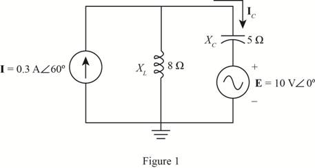
Using superposition, determine the current through the capacitance Xc in Fig. 19.106.
Expert Solution & Answer
Want to see the full answer?
Check out a sample textbook solution
Students have asked these similar questions
L.) Two identical coupled coils have an equivalent inductance of 100 mH when connected series aiding and 50 mH in series opposing. What are the values of the self-inductance L1 and L2?
a. 3.75 mH b. 375 mH c. 0.375 mH d. 37.50 mH
12. Two identical coupled coils have an equivalent inductance of 100 mH when connected series
aiding and 50 mH in series opposing. What are the values of the self-inductance L1 and L2?
a. 3.75 mH
www
www
b. 375 mH
c. 0.375 mH
d. 37.50 mH
ww
ww
ww
Problem 4
Given the circuit with input of 80HZ,
• Find the turns ratio
• Find Vp(sec)
• Find Vo when capacitor is removed.
• Find PIV rating
• Find Vripple (p-p)
• Find ripple factor (rf)
5:2
Use practical Si diode
Rurr
100Vrms
RL
3.3 k2
C
100 uF
lll
Chapter 19 Solutions
Introductory Circuit Analysis (13th Edition)
Ch. 19 - Using supeerposition, determine the current...Ch. 19 - Using superposition, determine the current through...Ch. 19 - Using superposition, determine the current IL for...Ch. 19 - Using superposition, determine the voltage across...Ch. 19 - Using superposition, determine the current through...Ch. 19 - Using superposition, find the sinusoidal...Ch. 19 - Using superposition, find the sinusoidal...Ch. 19 - Using superspostion, find the current I for the...Ch. 19 - Using superposition, determine the current IL...Ch. 19 - Using superposition, for the network of Fig....
Ch. 19 - Using superposition, determine the current IL for...Ch. 19 - Determine VL for the network of Fig. 19.116...Ch. 19 - Calculate the current I for the network of Fig....Ch. 19 - Find the voltage Vs for the network in Fig....Ch. 19 - Find the ThĂ©venin equivalent circuit for the...Ch. 19 - Find the Thevenin equivalent circuit for the...Ch. 19 - Find the Thevenin equivalent circuit for the...Ch. 19 - Find the Thevenin equivalent circuit for the...Ch. 19 - Find the Thevenin equivalent circuit for the...Ch. 19 - Find the Thevenin equivalent circuit for the...Ch. 19 - Find the ThĂªvenin equivalent circuit for the...Ch. 19 - Find the ThĂªvenin equivalent circuit for the...Ch. 19 - a. Find the ThĂ©venin equivalent circuit for the...Ch. 19 - a. Find the ThĂ©venin equivalent circuit for the...Ch. 19 - a. Find the ThĂ©venin equivalent circuit of the...Ch. 19 - Determine the ThĂ©venin equivalent circuit for the...Ch. 19 - Determine the ThĂ©venin equivalent circuit for the...Ch. 19 - Prob. 28PCh. 19 - Prob. 29PCh. 19 - Find the ThĂ©venin equivalent circuit for the...Ch. 19 - Determine the ThĂ©venin equivalent circuit for the...Ch. 19 - Prob. 32PCh. 19 - Find the ThĂ©venin equivalent circuit for the...Ch. 19 - Find the Norton equivalent circuit for the network...Ch. 19 - Find the Norton equivalent circuit for the network...Ch. 19 - Find the Norton equivalent circuit for the network...Ch. 19 - Find the Norton equivalent circuit for the portion...Ch. 19 - Find the Norton equivalent circuit for the portion...Ch. 19 - a. Find the Norton equivalent circuit for the...Ch. 19 - a. Find the Norton equivalent circuit for the...Ch. 19 - a. Find the Norton equivalent circuit for the...Ch. 19 - Determine the Norton equivalent circuit for the...Ch. 19 - Determine the Norton equivalent circuit for the...Ch. 19 - Find the Norton equivalent circuit for the network...Ch. 19 - Find the Norton equivalent circuit for the network...Ch. 19 - Prob. 46PCh. 19 - Prob. 47PCh. 19 - Find the load impedance ZL for the network of Fig....Ch. 19 - Find the load impedance ZL for the network of Fig....Ch. 19 - Find the load impedance ZL for the network of Fig....Ch. 19 - Find the load impedance ZL for the network of Fig....Ch. 19 - Prob. 52PCh. 19 - a. Determine the load impedance to replace the...Ch. 19 - a. Determine the load impedance to replace the...Ch. 19 - a. Determine the load impedance to replace the...Ch. 19 - Prob. 56PCh. 19 - a. For the network in Fig. 19.139, determine the...Ch. 19 - For the network in Fig. 19.140, determine two...Ch. 19 - Prob. 59PCh. 19 - Using Millmans theorem, determine the current...Ch. 19 - Prob. 61PCh. 19 - Determine the current IL for the network in Fig....Ch. 19 - Using schematics, determine V2 for the network in...Ch. 19 - Prob. 64PCh. 19 - Using schematics, plot the power to the R-C load...
Knowledge Booster


Learn more about
Need a deep-dive on the concept behind this application? Look no further. Learn more about this topic, electrical-engineering and related others by exploring similar questions and additional content below.Similar questions
- 12. Two identical coupled coils have an equivalent inductance of 100 mH when connected series aiding and 50 mH in series opposing. What are the values of the self-inductance L1 and L2? a. 3.75 mH b. 375 mH c. 0.375 mH d. 37.50 mHarrow_forward16. Two identical coils with self-inductance of 250 µH each are connected in series. When connected series aiding, the equivalent inductance is 550 µH and 450 µH when connected in series opposing. How much is the coupling coefficient of two coils? a. 0.2 b. 0.3 c. 0.1 d. 0.4arrow_forwardQ16 i. The capacitor sensor is a passive transducer and finds the application in displacement measurement system A three parallel plate capacitor is used in a measurement system, having an area of 200mm x 100cm. The distance between the upper and middle plates is 10mm, distance between middle plate and lower plate is 8mm. If the middle plate is moved down by 8mm with upper and middle plates unmoved, then calculate, Capacitance between upper plate and middle plate. a. b. Capacitance between middle plate and lower plate. ii. Draw the block diagram of a measurement system given the question Q16(i). Assume the sensitivities of C to V Converter is 2V/ 1pF with amplifier gain is 20. Then, calculate the total output voltage of the sensor.arrow_forward
- Name: 1) Find the total inductor of the following circuits between a and b? a) b) HW-8-AC- Inductor and capacitor CCC ІННЕ 2 25 mH m C 10 mH m HF 60 mH m 2DmH mm 30 mH 6 mH 8 mH 10 mH ele 2) Find the total capacitance of the following configuration assume, c=30 micro farad a) 8 mH m 5 mH 6 mH m m 8 mH 12 mH 4 mH CCarrow_forwardComplete the question completely and state the answer legibly.ıf you need use the multisim.thank you..arrow_forward13. If three 10 uF capacitors are connected in parallel, the net cararitance is A. 20 uF B. 30 UE C. 40 uF D. 50 uFarrow_forward
- Find the mutual inductance between two ideally coupled coils of 2 H and 8 H. 1. 16 H 2. 8 H 3. 4 H 4. 2 Harrow_forwardTranslator Determine: a) the value of the mutual inductance, b) the value of the current ??, and c) the complex power in the 6H inductor.arrow_forwardIna transmission line, to reduce the inductive coupling, one should Reduce the inductance None of the choices Reduce the capacitance Reduce the resistance and capacitance Reduce the resistancearrow_forward
arrow_back_ios
SEE MORE QUESTIONS
arrow_forward_ios
Recommended textbooks for you
 Introductory Circuit Analysis (13th Edition)Electrical EngineeringISBN:9780133923605Author:Robert L. BoylestadPublisher:PEARSON
 Delmar's Standard Textbook Of ElectricityElectrical EngineeringISBN:9781337900348Author:Stephen L. HermanPublisher:Cengage Learning
 Programmable Logic ControllersElectrical EngineeringISBN:9780073373843Author:Frank D. PetruzellaPublisher:McGraw-Hill Education
 Fundamentals of Electric CircuitsElectrical EngineeringISBN:9780078028229Author:Charles K Alexander, Matthew SadikuPublisher:McGraw-Hill Education
 Electric Circuits. (11th Edition)Electrical EngineeringISBN:9780134746968Author:James W. Nilsson, Susan RiedelPublisher:PEARSON
 Engineering ElectromagneticsElectrical EngineeringISBN:9780078028151Author:Hayt, William H. (william Hart), Jr, BUCK, John A.Publisher:Mcgraw-hill Education,
Introductory Circuit Analysis (13th Edition)
Electrical Engineering
ISBN:9780133923605
Author:Robert L. Boylestad
Publisher:PEARSON
Delmar's Standard Textbook Of Electricity
Electrical Engineering
ISBN:9781337900348
Author:Stephen L. Herman
Publisher:Cengage Learning
Programmable Logic Controllers
Electrical Engineering
ISBN:9780073373843
Author:Frank D. Petruzella
Publisher:McGraw-Hill Education
Fundamentals of Electric Circuits
Electrical Engineering
ISBN:9780078028229
Author:Charles K Alexander, Matthew Sadiku
Publisher:McGraw-Hill Education
Electric Circuits. (11th Edition)
Electrical Engineering
ISBN:9780134746968
Author:James W. Nilsson, Susan Riedel
Publisher:PEARSON
Engineering Electromagnetics
Electrical Engineering
ISBN:9780078028151
Author:Hayt, William H. (william Hart), Jr, BUCK, John A.
Publisher:Mcgraw-hill Education,
Introduction to Two-Port Networks; Author: ALL ABOUT ELECTRONICS;https://www.youtube.com/watch?v=ru2ItcD6unI;License: Standard Youtube License