
Introductory Circuit Analysis (13th Edition)
13th Edition
ISBN: 9780133923605
Author: Robert L. Boylestad
Publisher: PEARSON
expand_more
expand_more
format_list_bulleted
Concept explainers
Videos
Textbook Question
Chapter 18, Problem 8P
Write the mesh equations for the network of Fig. 18.68. Determine the current through the resistor R1.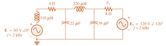
Expert Solution & Answer
Want to see the full answer?
Check out a sample textbook solution
Students have asked these similar questions
1,
E 48 V
RT, GT
R₁8k0
For the network above
a. Find the total conductance and resistance.
units
GT =
RT=
units
b. Determine I, and the current through each parallel branch (11 and 12).
ls =
1₁ =
¹2=
unts
units
R₂ 24 k
units
c. True or False, the sum of the brance currents equal the source current
x
AC Electricity:
For the bridge network in Fig.18.88:
a. Is the bridge balanced?
b. Using mesh analysis, determine the current through the capacitive reactance.
2-2: Find the Z parameters for the network shown below
71,
30
20
Chapter 18 Solutions
Introductory Circuit Analysis (13th Edition)
Ch. 18 - Discuss, in your own words, the difference between...Ch. 18 - Convert the voltage source in Fig. 18.62 to a...Ch. 18 - Convert the current source in Fig. 18.63 to a...Ch. 18 - Convert the votage source in Fig. 18.64(a) to a...Ch. 18 - Write the mesh equations for the network of Fig....Ch. 18 - Write the mesh equations for the network of Fig....Ch. 18 - Write the mesh equations for the network of Fig....Ch. 18 - Write the mesh equations for the network of Fig....Ch. 18 - Write the mesh equations for the network of Fig....Ch. 18 - Write the mesh equtions for the network of Fig....
Ch. 18 - Write the mesh equations for the network of Fig....Ch. 18 - Using mesh analysis, determine the current IL (in...Ch. 18 - Using mesh analysis, determine the current IL (in...Ch. 18 - Write the mesh equations for the network of Fig....Ch. 18 - Write the mesh equations for the network of...Ch. 18 - Write the mesh equations for the network of Fig....Ch. 18 - Determine the nodal voltages for the network of...Ch. 18 - Determine the nodal voltages for the network of...Ch. 18 - Determine the nodal voltages for the network of...Ch. 18 - Determine the nodal voltages for the network of...Ch. 18 - Determine the nodal voltages for the network of...Ch. 18 - Determine the nodal voltages for the network of...Ch. 18 - Determine the nodal votas for the network of Fig....Ch. 18 - Determine the nodal voltages for the network of...Ch. 18 - Write the nodal equations for the network in Fig....Ch. 18 - Write the nodal equations for the network of Fig....Ch. 18 - Write the nodal equations for the network of Fig....Ch. 18 - Write the nodal equations for the network of Fig....Ch. 18 - For the network of Fig. 18.87, determine the...Ch. 18 - For the bridge network in Fig. 18.88: Fig. 18.88...Ch. 18 - For the bridge network in Fig. 18.89: a. Is the...Ch. 18 - The Hay bridge in Fig. 18.90 is balanced. Using...Ch. 18 - Determine whether the Maxwell bridge in Fig. 18.91...Ch. 18 - Derive the balance equations (18.16) and (18.17)...Ch. 18 - Determine the balance equations for the inductance...Ch. 18 - Using the -YorY-conversion, determine the current...Ch. 18 - Using the -YorY-conversion, determine the current...Ch. 18 - Using the -YorY-conversion, determine the current...Ch. 18 - Using the -YorY-conversion, determine the current...Ch. 18 - Determine the mesh currents for the network of...Ch. 18 - Prob. 41PCh. 18 - Prob. 42PCh. 18 - Prob. 43PCh. 18 - Prob. 44PCh. 18 - Determine the nodal voltages for the network of...Ch. 18 - Determine the nodal voltages for the network of...Ch. 18 - Prob. 47PCh. 18 - Determine the nodal voltages for the network of...Ch. 18 - Determine the nodal voltages for the network of...
Knowledge Booster


Learn more about
Need a deep-dive on the concept behind this application? Look no further. Learn more about this topic, electrical-engineering and related others by exploring similar questions and additional content below.Similar questions
- 19 www 1 F ell 1 H Find z parameters And dont solve by looparrow_forward25. Find the load impedance Z₁, for the networks of Fig. 18.125 for maximum power to the load, and find the maximum power to the load. 51, R₁ R₂ www 1 kfl 2kf E $V20 R₁ FIG. 18.125 14 3.3 k Z₂arrow_forwardHW4C2 *10. Calculate the current I for the network of Fig. 18.118. 20V I = 1 mA R3 2 kl L = 2 mA Z VR, 5 k2 FIG. 18.118arrow_forward
- Below figue-3 shows the sequence network of the power system. Construct the Bus impedance matrix [us] for tis sem. Falow the bus order of 0- and 2-0 Reference bus 0.19 ll 0.1 0.1 0.2 Fig.3 eearrow_forward*14. For the circuit of Fig. 19.51: a. Find the total number of watts, volt-amperes reactive, and volt-amperes, and Fp. b. Find the current I.. c. Find the type of elements and their impedance in each box. (Assume that the elements within each box are in series.) Load 2 30 W 40 VAR (Z) Load 1 Load 3 E = 100 V 20° 200 W F₂ = 1 FIG. 19.51 100 VAR (L) F₂ = 0arrow_forwardIndividual loads on separate feeders of a large power system are often unbalanced. The loads of Y-connected generator, consisting of electric heaters, draw 150,100, and 50 A. Find the neutral currentarrow_forward
- 3. For the system given below a. Find the OLTFarrow_forwardthe following electrical circuit questions 1. Check the Reciprocity theorem for the network, with source and output response positions being at input and output terminals. 2.Draw an oriented graph for the network and obtain the corresponding incidence matrix. Then, find all cut sets and loops of the network. 3.For the network, assign arbitrary branch voltages and branch currents subject only to KVL and KCL constraints. Then, verify the conclusion of Tellegen’s theorem.arrow_forwardHW4C2 *2. Using superposition, determine the current I; for each network of Fig. 18.110. I 30 E = 10 VZ 90 1 = 0.6AZ 120 (b)arrow_forward
- s/۸,۱ 2 30 1[ ۳۸ ١:٥٢ م 4.jpg → *14. For the circuit of Fig. 19.51: a. Find the total number of watts, volt-amperes reactive, and volt-amperes, and Fp- b. Find the current I.. c. Find the type of elements and their impedance in each box. (Assume that the elements within each box are in series.) Load 2 30 W 40 VAR (L) L Load 1 Load 3 ... E = 100 V 20° O 200 W Fp = 1 FIG. 19.51 100 VAR (Z) = 0arrow_forwardFind the ABCD constants of the four-terminal network resulting when a resistance of 10 ohms is connected in series at the sending end of the four-terminal network are as follows: A = 0.96/_0deg B = 40/_90 deg ohms C = 0.002945/_90 mho D = 0.92/_0degarrow_forwardFor the network of Figure below, determine: а. Iв. b. Ic. c. VE. d. VCE. 아18V 6 ka 250 ka. VC +] VCE B= 130 600 ka 10 ka O-18 Varrow_forward
arrow_back_ios
SEE MORE QUESTIONS
arrow_forward_ios
Recommended textbooks for you
 Introductory Circuit Analysis (13th Edition)Electrical EngineeringISBN:9780133923605Author:Robert L. BoylestadPublisher:PEARSON
 Delmar's Standard Textbook Of ElectricityElectrical EngineeringISBN:9781337900348Author:Stephen L. HermanPublisher:Cengage Learning
 Programmable Logic ControllersElectrical EngineeringISBN:9780073373843Author:Frank D. PetruzellaPublisher:McGraw-Hill Education
 Fundamentals of Electric CircuitsElectrical EngineeringISBN:9780078028229Author:Charles K Alexander, Matthew SadikuPublisher:McGraw-Hill Education
 Electric Circuits. (11th Edition)Electrical EngineeringISBN:9780134746968Author:James W. Nilsson, Susan RiedelPublisher:PEARSON
 Engineering ElectromagneticsElectrical EngineeringISBN:9780078028151Author:Hayt, William H. (william Hart), Jr, BUCK, John A.Publisher:Mcgraw-hill Education,
Introductory Circuit Analysis (13th Edition)
Electrical Engineering
ISBN:9780133923605
Author:Robert L. Boylestad
Publisher:PEARSON
Delmar's Standard Textbook Of Electricity
Electrical Engineering
ISBN:9781337900348
Author:Stephen L. Herman
Publisher:Cengage Learning
Programmable Logic Controllers
Electrical Engineering
ISBN:9780073373843
Author:Frank D. Petruzella
Publisher:McGraw-Hill Education
Fundamentals of Electric Circuits
Electrical Engineering
ISBN:9780078028229
Author:Charles K Alexander, Matthew Sadiku
Publisher:McGraw-Hill Education
Electric Circuits. (11th Edition)
Electrical Engineering
ISBN:9780134746968
Author:James W. Nilsson, Susan Riedel
Publisher:PEARSON
Engineering Electromagnetics
Electrical Engineering
ISBN:9780078028151
Author:Hayt, William H. (william Hart), Jr, BUCK, John A.
Publisher:Mcgraw-hill Education,
Current Divider Rule; Author: Neso Academy;https://www.youtube.com/watch?v=hRU1mKWUehY;License: Standard YouTube License, CC-BY