
Introductory Circuit Analysis (13th Edition)
13th Edition
ISBN: 9780133923605
Author: Robert L. Boylestad
Publisher: PEARSON
expand_more
expand_more
format_list_bulleted
Concept explainers
Videos
Textbook Question
Chapter 18, Problem 3P
Convert the current source in Fig. 18.63 to a voltage source.
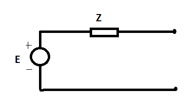
Fig. 18.63
Expert Solution & Answer
Want to see the full answer?
Check out a sample textbook solution
Students have asked these similar questions
HW4C2
4. Using superposition, find the sinusoidal expression for
the voltage Ve for the network of Fig. 18.112.
12 V
4A 20
FIG. 18.112
5485+19
100 2.0
K/s ll ?
すイ
1.jpg
17. For the network of Fig. 12.74:
a. Determine the mathematical expressions for the cur-
rent iz and the voltage V when the switch is closed.
b. Repeat part (a) if the switch is opened after a period
of five time constants has passed.
c. Sketch the waveforms of parts (a) and (b) on the same
set of axes.
10 k2
20 V
R
10 kn L 10 mH
VL
FIG. 12.74
Chapter 18 Solutions
Introductory Circuit Analysis (13th Edition)
Ch. 18 - Discuss, in your own words, the difference between...Ch. 18 - Convert the voltage source in Fig. 18.62 to a...Ch. 18 - Convert the current source in Fig. 18.63 to a...Ch. 18 - Convert the votage source in Fig. 18.64(a) to a...Ch. 18 - Write the mesh equations for the network of Fig....Ch. 18 - Write the mesh equations for the network of Fig....Ch. 18 - Write the mesh equations for the network of Fig....Ch. 18 - Write the mesh equations for the network of Fig....Ch. 18 - Write the mesh equations for the network of Fig....Ch. 18 - Write the mesh equtions for the network of Fig....
Ch. 18 - Write the mesh equations for the network of Fig....Ch. 18 - Using mesh analysis, determine the current IL (in...Ch. 18 - Using mesh analysis, determine the current IL (in...Ch. 18 - Write the mesh equations for the network of Fig....Ch. 18 - Write the mesh equations for the network of...Ch. 18 - Write the mesh equations for the network of Fig....Ch. 18 - Determine the nodal voltages for the network of...Ch. 18 - Determine the nodal voltages for the network of...Ch. 18 - Determine the nodal voltages for the network of...Ch. 18 - Determine the nodal voltages for the network of...Ch. 18 - Determine the nodal voltages for the network of...Ch. 18 - Determine the nodal voltages for the network of...Ch. 18 - Determine the nodal votas for the network of Fig....Ch. 18 - Determine the nodal voltages for the network of...Ch. 18 - Write the nodal equations for the network in Fig....Ch. 18 - Write the nodal equations for the network of Fig....Ch. 18 - Write the nodal equations for the network of Fig....Ch. 18 - Write the nodal equations for the network of Fig....Ch. 18 - For the network of Fig. 18.87, determine the...Ch. 18 - For the bridge network in Fig. 18.88: Fig. 18.88...Ch. 18 - For the bridge network in Fig. 18.89: a. Is the...Ch. 18 - The Hay bridge in Fig. 18.90 is balanced. Using...Ch. 18 - Determine whether the Maxwell bridge in Fig. 18.91...Ch. 18 - Derive the balance equations (18.16) and (18.17)...Ch. 18 - Determine the balance equations for the inductance...Ch. 18 - Using the -YorY-conversion, determine the current...Ch. 18 - Using the -YorY-conversion, determine the current...Ch. 18 - Using the -YorY-conversion, determine the current...Ch. 18 - Using the -YorY-conversion, determine the current...Ch. 18 - Determine the mesh currents for the network of...Ch. 18 - Prob. 41PCh. 18 - Prob. 42PCh. 18 - Prob. 43PCh. 18 - Prob. 44PCh. 18 - Determine the nodal voltages for the network of...Ch. 18 - Determine the nodal voltages for the network of...Ch. 18 - Prob. 47PCh. 18 - Determine the nodal voltages for the network of...Ch. 18 - Determine the nodal voltages for the network of...
Additional Engineering Textbook Solutions
Find more solutions based on key concepts
Design an ideal inverting op-amp circuit such that the voltage gain is Av=25 . The maximum current in any resis...
Microelectronics: Circuit Analysis and Design
Identify the type of input and output configuration for each diff-amp in Figure 18-35.
Electronics Fundamentals: Circuits, Devices & Applications
Explain the main function of each of the following major components of a PLC: a. Processor module (CPU) b. I/O ...
Programmable Logic Controllers
Analog Voltmeter Design Figure P2-98(a) shows a voltmeter circuit consisting of a D'Arsonval meter, two series ...
ANALYSIS+DESIGN OF LINEAR CIRCUITS(LL)
Three point charges of equal magnitude q, that will yield a zero net electric field at the origin.
Engineering Electromagnetics
Assume a telephone signal travels through a cable at two-thirds the speed of light. How long does it take the s...
Electric Circuits (10th Edition)
Knowledge Booster


Learn more about
Need a deep-dive on the concept behind this application? Look no further. Learn more about this topic, electrical-engineering and related others by exploring similar questions and additional content below.Similar questions
- *9. For the network of Fig. 19.48: a. Find the average power delivered to each element. b. Find the reactive power for each element. c. Find the apparent power for each element. d. Find the total number of watts, volt-amperes reactive, and volt-amperes, and the power factor F, of the cir- cuit. e. Sketch the power triangle. f. Find the energy dissipated by the resistor over one full cycle of the input voltage. g. Find the energy stored or returned by the capacitor and the inductor over one half-cycle of the power curve for each. L 000 0.1 H E = 50 V 20⁰ 100 μF R300 FIG. 19.48arrow_forwardIf the system has a non zero solution, then the value of a is O a. 6 O b. 1 Ос. 2 O d. 3arrow_forwardA newly constructed hydro-electric power station has an average annual rainfall of 193 cm. The catchment area is 260 square km with an available head of 32 m only 82% of the rainfall can be collected in and 5/8 of the impounded water is available for power the penstock off is 94% turbine off is 78% and generator off is 88%. Determine the average power that could be generated (kw)arrow_forward
- Identify Which carries, large quantities of electrical energy from the following. a. utilization O b. distribution c. Primary transmission O d. Generationarrow_forwardCompare and contrast diesel power plant with one of the existing power plant in the country in terms of: c. Effects to environmentarrow_forwardx (23) WhatsApp 4 Meet-hpd-sdbt-qho الأخبار Google hilj> YouTube Gmail SEESLENENS The step angle for a stepper motor drive having 10 number of poles and 75 rotor teeths is Harmonics generated due to the presence of switching power electronic devices are called ofarrow_forward
- Transform 4A to independent voltage source and then determine the voltage drop at 2ohmsarrow_forward17. For the network of Fig. 12.74: a. Determine the mathematical expressions for the cur- rent iz and the voltage V when the switch is closed. b. Repeat part (a) if the switch is opened after a period of five time constants has passed. c. Sketch the waveforms of parts (a) and (b) on the same set of axes. R1 10 k2 20 V R10 kn 10 mH VL FIG. 12.74 llarrow_forwardA three phase bridge rectifier has a purely resistive load. The rectifier delivers 45 A current at an average output voltage of Vdc 300 V. The rms output voltage Vrms is equal to: Select one: а. 300.25V O b. 275.5V О с. 180.1V O d. 240.15Varrow_forward
- Determine I, and Vx. 60V (+ 102 M 122 + Vx 201 18.2arrow_forwardFor the following system shown below, determine the characteristic equation, the rise time, settling time, and also calculate the value of K and j so that the peak time is 1 sec,maximum overshoot is 0.2 when a unit step input is applied.arrow_forwardCombined Cycle Power Plants are having higher efficiency comparing to open cycle Power plant because of. O a. Availability of compressor O b. Availability of HRSG O .Availability of Gas Turbine O d. Availability of Filter Pumparrow_forward
arrow_back_ios
SEE MORE QUESTIONS
arrow_forward_ios
Recommended textbooks for you

How Thermistors Work - The Learning Circuit; Author: element14 presents;https://www.youtube.com/watch?v=g683mTSZ2i0;License: Standard Youtube License