
Introductory Circuit Analysis (13th Edition)
13th Edition
ISBN: 9780133923605
Author: Robert L. Boylestad
Publisher: PEARSON
expand_more
expand_more
format_list_bulleted
Concept explainers
Videos
Textbook Question
Chapter 18, Problem 5P
Write the mesh equations for the network of Fig. 18.65. Determine the current through the resistor R.
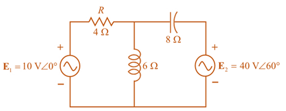
Fig. 18.65
Expert Solution & Answer
Want to see the full answer?
Check out a sample textbook solution
Students have asked these similar questions
HW4C2
4. Using superposition, find the sinusoidal expression for
the voltage Ve for the network of Fig. 18.112.
12 V
4A 20
FIG. 18.112
5485+19
1,
E 48 V
RT, GT
R₁8k0
For the network above
a. Find the total conductance and resistance.
units
GT =
RT=
units
b. Determine I, and the current through each parallel branch (11 and 12).
ls =
1₁ =
¹2=
unts
units
R₂ 24 k
units
c. True or False, the sum of the brance currents equal the source current
x
Chapter 18 Solutions
Introductory Circuit Analysis (13th Edition)
Ch. 18 - Discuss, in your own words, the difference between...Ch. 18 - Convert the voltage source in Fig. 18.62 to a...Ch. 18 - Convert the current source in Fig. 18.63 to a...Ch. 18 - Convert the votage source in Fig. 18.64(a) to a...Ch. 18 - Write the mesh equations for the network of Fig....Ch. 18 - Write the mesh equations for the network of Fig....Ch. 18 - Write the mesh equations for the network of Fig....Ch. 18 - Write the mesh equations for the network of Fig....Ch. 18 - Write the mesh equations for the network of Fig....Ch. 18 - Write the mesh equtions for the network of Fig....
Ch. 18 - Write the mesh equations for the network of Fig....Ch. 18 - Using mesh analysis, determine the current IL (in...Ch. 18 - Using mesh analysis, determine the current IL (in...Ch. 18 - Write the mesh equations for the network of Fig....Ch. 18 - Write the mesh equations for the network of...Ch. 18 - Write the mesh equations for the network of Fig....Ch. 18 - Determine the nodal voltages for the network of...Ch. 18 - Determine the nodal voltages for the network of...Ch. 18 - Determine the nodal voltages for the network of...Ch. 18 - Determine the nodal voltages for the network of...Ch. 18 - Determine the nodal voltages for the network of...Ch. 18 - Determine the nodal voltages for the network of...Ch. 18 - Determine the nodal votas for the network of Fig....Ch. 18 - Determine the nodal voltages for the network of...Ch. 18 - Write the nodal equations for the network in Fig....Ch. 18 - Write the nodal equations for the network of Fig....Ch. 18 - Write the nodal equations for the network of Fig....Ch. 18 - Write the nodal equations for the network of Fig....Ch. 18 - For the network of Fig. 18.87, determine the...Ch. 18 - For the bridge network in Fig. 18.88: Fig. 18.88...Ch. 18 - For the bridge network in Fig. 18.89: a. Is the...Ch. 18 - The Hay bridge in Fig. 18.90 is balanced. Using...Ch. 18 - Determine whether the Maxwell bridge in Fig. 18.91...Ch. 18 - Derive the balance equations (18.16) and (18.17)...Ch. 18 - Determine the balance equations for the inductance...Ch. 18 - Using the -YorY-conversion, determine the current...Ch. 18 - Using the -YorY-conversion, determine the current...Ch. 18 - Using the -YorY-conversion, determine the current...Ch. 18 - Using the -YorY-conversion, determine the current...Ch. 18 - Determine the mesh currents for the network of...Ch. 18 - Prob. 41PCh. 18 - Prob. 42PCh. 18 - Prob. 43PCh. 18 - Prob. 44PCh. 18 - Determine the nodal voltages for the network of...Ch. 18 - Determine the nodal voltages for the network of...Ch. 18 - Prob. 47PCh. 18 - Determine the nodal voltages for the network of...Ch. 18 - Determine the nodal voltages for the network of...
Additional Engineering Textbook Solutions
Find more solutions based on key concepts
The current source in the circuit shown generates the current pulse
Find (a) v (0); (b) the instant of time gr...
Electric Circuits. (11th Edition)
Does the severity of an electric shock increase ordecrease with eh of the following changes? a. A decrease in t...
Electric Motors and Control Systems
Identify the type of input and output configuration for each diff-amp in Figure 18-35.
Electronics Fundamentals: Circuits, Devices & Applications
Explain the main function of each of the following major components of a PLC: a. Processor module (CPU) b. I/O ...
Programmable Logic Controllers
Find I0 and I1 in the circuit in Fig.P2.12.
Basic Engineering Circuit Analysis
With respect to the circuit in Fig. 5.90, (a) employ Thévenin’s theorem to determine the equivalent network see...
Loose Leaf for Engineering Circuit Analysis Format: Loose-leaf
Knowledge Booster


Learn more about
Need a deep-dive on the concept behind this application? Look no further. Learn more about this topic, electrical-engineering and related others by exploring similar questions and additional content below.Similar questions
- Find iy. Using mesh analysis or nodal analysis.arrow_forward25. Find the load impedance Z₁, for the networks of Fig. 18.125 for maximum power to the load, and find the maximum power to the load. 51, R₁ R₂ www 1 kfl 2kf E $V20 R₁ FIG. 18.125 14 3.3 k Z₂arrow_forwardHomework 1: Find ABCD constant for system bellow assume transmission line is medium (take T- method) T.L IR Darrow_forward
- AaBbCcDc AaBbCcDc AaBbC AaBbCc A aB AaBl U - abe x, x I Normal I No Spaci.. Heading 1 Heading 2 Title Subt Font Paragraph Styles Q16. Find out the bus admittance matrix [Ybus] of the power system as shown in Fig.2.Data of the system are given in table-1 FL20, AY2020-2021. Page 3 1: Per unit impedances and line charging for sample power system shown in Fig. 1 Table Bus code i-k Impedance Z Line charging Y ik2 0.01+ 0.0 3 0.0 4 0.25 0.03+ 0.14 1-2 0.03 0.025 0.020 1-3 Fig. 1 3 bus sample power system. 2-3 0.874-j1.71 - 0.39+0.65 -0.19+j0.96 -0.21+j0.77 0.768-j2.95 0.47-j1.91 -0.32+j0.95 -0.16-j0.99 - 0.32+0.95 -0.52+j0.75 -0.188-j0.93 O 0.93-j1.61 0.57-j1.81 -0.32+j0.85 -0.168+j0.96 - 0.36+j0.65 0.56-j1.95 -0.31+j0.92 -0.2+j0.69 -0.31-j0.89 -0.41+j0.92 0.77-j1.85 O None of the above 0.53-i1.91 -0.21+i0.98 sh (U.S.)arrow_forwardProblem 3 :. Using superposition, determine the current I, for each network of Fig. 18.110. Xe :50 I- 0.3 AZ 60° Z 10° + E - 10 VZ0°arrow_forwardIndividual loads on separate feeders of a large power system are often unbalanced. The loads of Y-connected generator, consisting of electric heaters, draw 150,100, and 50 A. Find the neutral currentarrow_forward
- 1. A 3 phase feeder having a resistance of 3 ohms and a reactance of 10ohms supplies a load of 2 MW at 0.85 pf lagging. The receiving end voltage is maintained at 11kV by means of a static condenser drawing 2.1 MVAR from the line. Calculate the sending end voltage and p.f. Also find the voltage regulation and efficiency of the feeder. Assume Delta connected.arrow_forwardDetermine I, and Vx. 60V (+ 102 M 122 + Vx 201 18.2arrow_forward*9. For the network of Fig. 19.48: a. Find the average power delivered to each element. b. Find the reactive power for each element. c. Find the apparent power for each element. d. Find the total number of watts, volt-amperes reactive, and volt-amperes, and the power factor F, of the cir- cuit. e. Sketch the power triangle. f. Find the energy dissipated by the resistor over one full cycle of the input voltage. g. Find the energy stored or returned by the capacitor and the inductor over one half-cycle of the power curve for each. L 000 0.1 H E = 50 V 20⁰ 100 μF R300 FIG. 19.48arrow_forward
- 3. A single-phase 50 Hz generator supplies an inductive load of 5 MW at a power factor of 0-866 lagging by means of an overhead transmission :"line 20 km long. The line resistance and inductance are 0:0195 ohm and 0:63 mH per km The voltage at the receiving end is réquired to be kept.constant at 10 kV. (a) Find the sendingend voltage and voltage regulation of the line.arrow_forwardRenewable / Secondary Sources of power except А. Solar Power В. Wind Power C. Nuclear Power D. Нydro Powerarrow_forwardIbc find the load current Vca find the line voltage Calculate the complex power on the transmission linearrow_forward
arrow_back_ios
SEE MORE QUESTIONS
arrow_forward_ios
Recommended textbooks for you
 Power System Analysis and Design (MindTap Course ...Electrical EngineeringISBN:9781305632134Author:J. Duncan Glover, Thomas Overbye, Mulukutla S. SarmaPublisher:Cengage Learning
Power System Analysis and Design (MindTap Course ...
Electrical Engineering
ISBN:9781305632134
Author:J. Duncan Glover, Thomas Overbye, Mulukutla S. Sarma
Publisher:Cengage Learning
Kirchhoff's Rules of Electrical Circuits; Author: Flipping Physics;https://www.youtube.com/watch?v=d0O-KUKP4nM;License: Standard YouTube License, CC-BY