
Introductory Circuit Analysis (13th Edition)
13th Edition
ISBN: 9780133923605
Author: Robert L. Boylestad
Publisher: PEARSON
expand_more
expand_more
format_list_bulleted
Concept explainers
Videos
Textbook Question
Chapter 18, Problem 11P
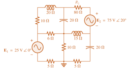
Write the mesh equations for the network of Fig. 18.71. Determine the current through the resistor R1.
Expert Solution & Answer
Want to see the full answer?
Check out a sample textbook solution
Students have asked these similar questions
AC Electricity:
For the bridge network in Fig.18.88:
a. Is the bridge balanced?
b. Using mesh analysis, determine the current through the capacitive reactance.
2-2: Find the Z parameters for the network shown below
71,
30
20
I need help understanding this question..
Write the mesh equations for the network Fig.18.68. Determine the current through the resistor R1.
Chapter 18 Solutions
Introductory Circuit Analysis (13th Edition)
Ch. 18 - Discuss, in your own words, the difference between...Ch. 18 - Convert the voltage source in Fig. 18.62 to a...Ch. 18 - Convert the current source in Fig. 18.63 to a...Ch. 18 - Convert the votage source in Fig. 18.64(a) to a...Ch. 18 - Write the mesh equations for the network of Fig....Ch. 18 - Write the mesh equations for the network of Fig....Ch. 18 - Write the mesh equations for the network of Fig....Ch. 18 - Write the mesh equations for the network of Fig....Ch. 18 - Write the mesh equations for the network of Fig....Ch. 18 - Write the mesh equtions for the network of Fig....
Ch. 18 - Write the mesh equations for the network of Fig....Ch. 18 - Using mesh analysis, determine the current IL (in...Ch. 18 - Using mesh analysis, determine the current IL (in...Ch. 18 - Write the mesh equations for the network of Fig....Ch. 18 - Write the mesh equations for the network of...Ch. 18 - Write the mesh equations for the network of Fig....Ch. 18 - Determine the nodal voltages for the network of...Ch. 18 - Determine the nodal voltages for the network of...Ch. 18 - Determine the nodal voltages for the network of...Ch. 18 - Determine the nodal voltages for the network of...Ch. 18 - Determine the nodal voltages for the network of...Ch. 18 - Determine the nodal voltages for the network of...Ch. 18 - Determine the nodal votas for the network of Fig....Ch. 18 - Determine the nodal voltages for the network of...Ch. 18 - Write the nodal equations for the network in Fig....Ch. 18 - Write the nodal equations for the network of Fig....Ch. 18 - Write the nodal equations for the network of Fig....Ch. 18 - Write the nodal equations for the network of Fig....Ch. 18 - For the network of Fig. 18.87, determine the...Ch. 18 - For the bridge network in Fig. 18.88: Fig. 18.88...Ch. 18 - For the bridge network in Fig. 18.89: a. Is the...Ch. 18 - The Hay bridge in Fig. 18.90 is balanced. Using...Ch. 18 - Determine whether the Maxwell bridge in Fig. 18.91...Ch. 18 - Derive the balance equations (18.16) and (18.17)...Ch. 18 - Determine the balance equations for the inductance...Ch. 18 - Using the -YorY-conversion, determine the current...Ch. 18 - Using the -YorY-conversion, determine the current...Ch. 18 - Using the -YorY-conversion, determine the current...Ch. 18 - Using the -YorY-conversion, determine the current...Ch. 18 - Determine the mesh currents for the network of...Ch. 18 - Prob. 41PCh. 18 - Prob. 42PCh. 18 - Prob. 43PCh. 18 - Prob. 44PCh. 18 - Determine the nodal voltages for the network of...Ch. 18 - Determine the nodal voltages for the network of...Ch. 18 - Prob. 47PCh. 18 - Determine the nodal voltages for the network of...Ch. 18 - Determine the nodal voltages for the network of...
Knowledge Booster


Learn more about
Need a deep-dive on the concept behind this application? Look no further. Learn more about this topic, electrical-engineering and related others by exploring similar questions and additional content below.Similar questions
- Individual loads on separate feeders of a large power system are often unbalanced. The loads of Y-connected generator, consisting of electric heaters, draw 150,100, and 50 A. Find the neutral currentarrow_forwardBelow figue-3 shows the sequence network of the power system. Construct the Bus impedance matrix [us] for tis sem. Falow the bus order of 0- and 2-0 Reference bus 0.19 ll 0.1 0.1 0.2 Fig.3 eearrow_forward*14. For the circuit of Fig. 19.51: a. Find the total number of watts, volt-amperes reactive, and volt-amperes, and Fp. b. Find the current I.. c. Find the type of elements and their impedance in each box. (Assume that the elements within each box are in series.) Load 2 30 W 40 VAR (Z) Load 1 Load 3 E = 100 V 20° 200 W F₂ = 1 FIG. 19.51 100 VAR (L) F₂ = 0arrow_forward
- For the network of Figure below, determine: а. Iв. b. Ic. c. VE. d. VCE. 아18V 6 ka 250 ka. VC +] VCE B= 130 600 ka 10 ka O-18 Varrow_forwardQ.29: For the two-port electric network shown in figure beside, calculate the maximum load power? Z11=122 Z1F-82 Z21=62 Z22-142 5A 1052 122 wwarrow_forwards/۸,۱ 2 30 1[ ۳۸ ١:٥٢ م 4.jpg → *14. For the circuit of Fig. 19.51: a. Find the total number of watts, volt-amperes reactive, and volt-amperes, and Fp- b. Find the current I.. c. Find the type of elements and their impedance in each box. (Assume that the elements within each box are in series.) Load 2 30 W 40 VAR (L) L Load 1 Load 3 ... E = 100 V 20° O 200 W Fp = 1 FIG. 19.51 100 VAR (Z) = 0arrow_forward
- HW4C2 *10. Calculate the current I for the network of Fig. 18.118. 20V I = 1 mA R3 2 kl L = 2 mA Z VR, 5 k2 FIG. 18.118arrow_forward*14. For the circuit of Fig. 19.51: a. Find the total number of watts, volt-amperes reactive, and volt-amperes, and F. b. Find the current I.. c. Find the type of elements and their impedance in each box. (Assume that the elements within each box are in series.) Load 2 30 W 40 VAR (L) Load 1 Load 3 E = 100 V 20 (2) 200 W Fp = 1 FIG. 19.51 100 VAR (L) Fp = 0arrow_forwardQuestion: Design Marx Generator for the specifications of your own choice also derived its each parametersarrow_forward
arrow_back_ios
SEE MORE QUESTIONS
arrow_forward_ios
Recommended textbooks for you
 Introductory Circuit Analysis (13th Edition)Electrical EngineeringISBN:9780133923605Author:Robert L. BoylestadPublisher:PEARSON
 Delmar's Standard Textbook Of ElectricityElectrical EngineeringISBN:9781337900348Author:Stephen L. HermanPublisher:Cengage Learning
 Programmable Logic ControllersElectrical EngineeringISBN:9780073373843Author:Frank D. PetruzellaPublisher:McGraw-Hill Education
 Fundamentals of Electric CircuitsElectrical EngineeringISBN:9780078028229Author:Charles K Alexander, Matthew SadikuPublisher:McGraw-Hill Education
 Electric Circuits. (11th Edition)Electrical EngineeringISBN:9780134746968Author:James W. Nilsson, Susan RiedelPublisher:PEARSON
 Engineering ElectromagneticsElectrical EngineeringISBN:9780078028151Author:Hayt, William H. (william Hart), Jr, BUCK, John A.Publisher:Mcgraw-hill Education,
Introductory Circuit Analysis (13th Edition)
Electrical Engineering
ISBN:9780133923605
Author:Robert L. Boylestad
Publisher:PEARSON
Delmar's Standard Textbook Of Electricity
Electrical Engineering
ISBN:9781337900348
Author:Stephen L. Herman
Publisher:Cengage Learning
Programmable Logic Controllers
Electrical Engineering
ISBN:9780073373843
Author:Frank D. Petruzella
Publisher:McGraw-Hill Education
Fundamentals of Electric Circuits
Electrical Engineering
ISBN:9780078028229
Author:Charles K Alexander, Matthew Sadiku
Publisher:McGraw-Hill Education
Electric Circuits. (11th Edition)
Electrical Engineering
ISBN:9780134746968
Author:James W. Nilsson, Susan Riedel
Publisher:PEARSON
Engineering Electromagnetics
Electrical Engineering
ISBN:9780078028151
Author:Hayt, William H. (william Hart), Jr, BUCK, John A.
Publisher:Mcgraw-hill Education,
Current Divider Rule; Author: Neso Academy;https://www.youtube.com/watch?v=hRU1mKWUehY;License: Standard YouTube License, CC-BY