
Introductory Circuit Analysis (13th Edition)
13th Edition
ISBN: 9780133923605
Author: Robert L. Boylestad
Publisher: PEARSON
expand_more
expand_more
format_list_bulleted
Concept explainers
Videos
Textbook Question
Chapter 18, Problem 29P
For the network of Fig. 18.87, determine the voltage VL in terms of the voltage E.
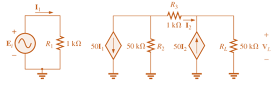
Fig. 18.87
Expert Solution & Answer
Want to see the full answer?
Check out a sample textbook solution
Students have asked these similar questions
HW4C2
4. Using superposition, find the sinusoidal expression for
the voltage Ve for the network of Fig. 18.112.
12 V
4A 20
FIG. 18.112
5485+19
Determine I, and Vx.
60V (+
102
M
122
+
Vx 201
18.2
Chapter 18 Solutions
Introductory Circuit Analysis (13th Edition)
Ch. 18 - Discuss, in your own words, the difference between...Ch. 18 - Convert the voltage source in Fig. 18.62 to a...Ch. 18 - Convert the current source in Fig. 18.63 to a...Ch. 18 - Convert the votage source in Fig. 18.64(a) to a...Ch. 18 - Write the mesh equations for the network of Fig....Ch. 18 - Write the mesh equations for the network of Fig....Ch. 18 - Write the mesh equations for the network of Fig....Ch. 18 - Write the mesh equations for the network of Fig....Ch. 18 - Write the mesh equations for the network of Fig....Ch. 18 - Write the mesh equtions for the network of Fig....
Ch. 18 - Write the mesh equations for the network of Fig....Ch. 18 - Using mesh analysis, determine the current IL (in...Ch. 18 - Using mesh analysis, determine the current IL (in...Ch. 18 - Write the mesh equations for the network of Fig....Ch. 18 - Write the mesh equations for the network of...Ch. 18 - Write the mesh equations for the network of Fig....Ch. 18 - Determine the nodal voltages for the network of...Ch. 18 - Determine the nodal voltages for the network of...Ch. 18 - Determine the nodal voltages for the network of...Ch. 18 - Determine the nodal voltages for the network of...Ch. 18 - Determine the nodal voltages for the network of...Ch. 18 - Determine the nodal voltages for the network of...Ch. 18 - Determine the nodal votas for the network of Fig....Ch. 18 - Determine the nodal voltages for the network of...Ch. 18 - Write the nodal equations for the network in Fig....Ch. 18 - Write the nodal equations for the network of Fig....Ch. 18 - Write the nodal equations for the network of Fig....Ch. 18 - Write the nodal equations for the network of Fig....Ch. 18 - For the network of Fig. 18.87, determine the...Ch. 18 - For the bridge network in Fig. 18.88: Fig. 18.88...Ch. 18 - For the bridge network in Fig. 18.89: a. Is the...Ch. 18 - The Hay bridge in Fig. 18.90 is balanced. Using...Ch. 18 - Determine whether the Maxwell bridge in Fig. 18.91...Ch. 18 - Derive the balance equations (18.16) and (18.17)...Ch. 18 - Determine the balance equations for the inductance...Ch. 18 - Using the -YorY-conversion, determine the current...Ch. 18 - Using the -YorY-conversion, determine the current...Ch. 18 - Using the -YorY-conversion, determine the current...Ch. 18 - Using the -YorY-conversion, determine the current...Ch. 18 - Determine the mesh currents for the network of...Ch. 18 - Prob. 41PCh. 18 - Prob. 42PCh. 18 - Prob. 43PCh. 18 - Prob. 44PCh. 18 - Determine the nodal voltages for the network of...Ch. 18 - Determine the nodal voltages for the network of...Ch. 18 - Prob. 47PCh. 18 - Determine the nodal voltages for the network of...Ch. 18 - Determine the nodal voltages for the network of...
Knowledge Booster


Learn more about
Need a deep-dive on the concept behind this application? Look no further. Learn more about this topic, electrical-engineering and related others by exploring similar questions and additional content below.Similar questions
- 1, E 48 V RT, GT R₁8k0 For the network above a. Find the total conductance and resistance. units GT = RT= units b. Determine I, and the current through each parallel branch (11 and 12). ls = 1₁ = ¹2= unts units R₂ 24 k units c. True or False, the sum of the brance currents equal the source current xarrow_forward25. Find the load impedance Z₁, for the networks of Fig. 18.125 for maximum power to the load, and find the maximum power to the load. 51, R₁ R₂ www 1 kfl 2kf E $V20 R₁ FIG. 18.125 14 3.3 k Z₂arrow_forward3. A single-phase 50 Hz generator supplies an inductive load of 5 MW at a power factor of 0-866 lagging by means of an overhead transmission :"line 20 km long. The line resistance and inductance are 0:0195 ohm and 0:63 mH per km The voltage at the receiving end is réquired to be kept.constant at 10 kV. (a) Find the sendingend voltage and voltage regulation of the line.arrow_forward
- Problem 3 :. Using superposition, determine the current I, for each network of Fig. 18.110. Xe :50 I- 0.3 AZ 60° Z 10° + E - 10 VZ0°arrow_forward2. In the below system, Va = 480260, Zline = 0.1j, Zload = 12.6+j18.3. a) Find phase currents (the current passing through lines) b) Find the voltage across each leg of the load. c) Find the load power (load power means 3-phase power) √6 Zeine m Va m Zloadarrow_forward*9. For the network of Fig. 19.48: a. Find the average power delivered to each element. b. Find the reactive power for each element. c. Find the apparent power for each element. d. Find the total number of watts, volt-amperes reactive, and volt-amperes, and the power factor F, of the cir- cuit. e. Sketch the power triangle. f. Find the energy dissipated by the resistor over one full cycle of the input voltage. g. Find the energy stored or returned by the capacitor and the inductor over one half-cycle of the power curve for each. L 000 0.1 H E = 50 V 20⁰ 100 μF R300 FIG. 19.48arrow_forward
- unpack the brackets 114.651241) (52 +0.8425 +2.93) (5+5) 822arrow_forwardAaBbCcDc AaBbCcDc AaBbC AaBbCc A aB AaBl U - abe x, x I Normal I No Spaci.. Heading 1 Heading 2 Title Subt Font Paragraph Styles Q16. Find out the bus admittance matrix [Ybus] of the power system as shown in Fig.2.Data of the system are given in table-1 FL20, AY2020-2021. Page 3 1: Per unit impedances and line charging for sample power system shown in Fig. 1 Table Bus code i-k Impedance Z Line charging Y ik2 0.01+ 0.0 3 0.0 4 0.25 0.03+ 0.14 1-2 0.03 0.025 0.020 1-3 Fig. 1 3 bus sample power system. 2-3 0.874-j1.71 - 0.39+0.65 -0.19+j0.96 -0.21+j0.77 0.768-j2.95 0.47-j1.91 -0.32+j0.95 -0.16-j0.99 - 0.32+0.95 -0.52+j0.75 -0.188-j0.93 O 0.93-j1.61 0.57-j1.81 -0.32+j0.85 -0.168+j0.96 - 0.36+j0.65 0.56-j1.95 -0.31+j0.92 -0.2+j0.69 -0.31-j0.89 -0.41+j0.92 0.77-j1.85 O None of the above 0.53-i1.91 -0.21+i0.98 sh (U.S.)arrow_forwardFor a given power transfer which of the following is true. O Delta is associated with larger line voltage O Delta is associated with larger line current O Star is associated with larger line current O Conductors in delta system have smaller cross sectional area A Transformer having 1400 Primary turns connected to a 252 V a.c. supply. For a secondary Voltage of 416 V, the number of Secondary Turns should be No. of Turns in the Secondary hp fs 19 11 44 f10 & 7 8 V 60arrow_forward
- The ABCD constants of a 60 Hz, 3-phase long transmission lines are as follows B = 191.62/79.1⁰ C = 0.0012/90.4° A=D=0.877/1.57° This supplies 100 MW load at 230 kV with 90% power factor. What is the sending voltage ? A. 248 KV B. 245 KV C 269 KV D. 238 KVarrow_forward(b) A three-phase 50 Hz transmission line with a length of 150 km is connected to a load of 2 MW with 0.85 lagging power factor at 132 kV. The A, B, C and D parameter of the л-circuit representation of line are given as follows: A=D=0.983 0.393°, B=80.782 68.2°, C= 4.46 x 10 Z90.2° (i) (ii) Calculate the sending end voltage and current. Determine the voltage regulation.arrow_forwardConsider the configuration from Problem 1, except that each phase of the transmission line has an impedance of ݆1.5 Ω. a. Determine the line currents. b. Determine the line‐neutral voltage for each branch of the 3Φ load. c. Determine the complex power consumed by the 3Φ load. d. Determine the complex power produced by the 3Φ source. e. Determine the power consumed by the transmission line. f. Determine the load power factor, and the power factor observed by the source. problem 1 : Each leg of a symmetric, Y‐connected, 3Φ load has an impedance of 10∠36.87° Ω, and is connected to A 60 Hz, balanced, positive‐sequence, Y‐connected 3Φ voltage source with Vrms .3Φ source via an ideal transmission line (that is, the connection from the source to the load has zero impedance).arrow_forward
arrow_back_ios
SEE MORE QUESTIONS
arrow_forward_ios
Recommended textbooks for you
 Power System Analysis and Design (MindTap Course ...Electrical EngineeringISBN:9781305632134Author:J. Duncan Glover, Thomas Overbye, Mulukutla S. SarmaPublisher:Cengage Learning
Power System Analysis and Design (MindTap Course ...
Electrical Engineering
ISBN:9781305632134
Author:J. Duncan Glover, Thomas Overbye, Mulukutla S. Sarma
Publisher:Cengage Learning
Kirchhoff's Rules of Electrical Circuits; Author: Flipping Physics;https://www.youtube.com/watch?v=d0O-KUKP4nM;License: Standard YouTube License, CC-BY