
Introductory Circuit Analysis (13th Edition)
13th Edition
ISBN: 9780133923605
Author: Robert L. Boylestad
Publisher: PEARSON
expand_more
expand_more
format_list_bulleted
Concept explainers
Videos
Textbook Question
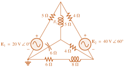
Chapter 18, Problem 10P
Write the mesh equtions for the network of Fig. 18.70. Determine the current through the resistor R1.
Expert Solution & Answer
Want to see the full answer?
Check out a sample textbook solution
Students have asked these similar questions
I need help understanding this question..
Write the mesh equations for the network Fig.18.68. Determine the current through the resistor R1.
HW4C2
*10. Calculate the current I for the network of Fig. 18.118.
20V
I = 1 mA
R3 2 kl
L = 2 mA Z
VR,
5 k2
FIG. 18.118
19
www
1 F
ell
1 H
Find z
parameters
And dont solve
by loop
Chapter 18 Solutions
Introductory Circuit Analysis (13th Edition)
Ch. 18 - Discuss, in your own words, the difference between...Ch. 18 - Convert the voltage source in Fig. 18.62 to a...Ch. 18 - Convert the current source in Fig. 18.63 to a...Ch. 18 - Convert the votage source in Fig. 18.64(a) to a...Ch. 18 - Write the mesh equations for the network of Fig....Ch. 18 - Write the mesh equations for the network of Fig....Ch. 18 - Write the mesh equations for the network of Fig....Ch. 18 - Write the mesh equations for the network of Fig....Ch. 18 - Write the mesh equations for the network of Fig....Ch. 18 - Write the mesh equtions for the network of Fig....
Ch. 18 - Write the mesh equations for the network of Fig....Ch. 18 - Using mesh analysis, determine the current IL (in...Ch. 18 - Using mesh analysis, determine the current IL (in...Ch. 18 - Write the mesh equations for the network of Fig....Ch. 18 - Write the mesh equations for the network of...Ch. 18 - Write the mesh equations for the network of Fig....Ch. 18 - Determine the nodal voltages for the network of...Ch. 18 - Determine the nodal voltages for the network of...Ch. 18 - Determine the nodal voltages for the network of...Ch. 18 - Determine the nodal voltages for the network of...Ch. 18 - Determine the nodal voltages for the network of...Ch. 18 - Determine the nodal voltages for the network of...Ch. 18 - Determine the nodal votas for the network of Fig....Ch. 18 - Determine the nodal voltages for the network of...Ch. 18 - Write the nodal equations for the network in Fig....Ch. 18 - Write the nodal equations for the network of Fig....Ch. 18 - Write the nodal equations for the network of Fig....Ch. 18 - Write the nodal equations for the network of Fig....Ch. 18 - For the network of Fig. 18.87, determine the...Ch. 18 - For the bridge network in Fig. 18.88: Fig. 18.88...Ch. 18 - For the bridge network in Fig. 18.89: a. Is the...Ch. 18 - The Hay bridge in Fig. 18.90 is balanced. Using...Ch. 18 - Determine whether the Maxwell bridge in Fig. 18.91...Ch. 18 - Derive the balance equations (18.16) and (18.17)...Ch. 18 - Determine the balance equations for the inductance...Ch. 18 - Using the -YorY-conversion, determine the current...Ch. 18 - Using the -YorY-conversion, determine the current...Ch. 18 - Using the -YorY-conversion, determine the current...Ch. 18 - Using the -YorY-conversion, determine the current...Ch. 18 - Determine the mesh currents for the network of...Ch. 18 - Prob. 41PCh. 18 - Prob. 42PCh. 18 - Prob. 43PCh. 18 - Prob. 44PCh. 18 - Determine the nodal voltages for the network of...Ch. 18 - Determine the nodal voltages for the network of...Ch. 18 - Prob. 47PCh. 18 - Determine the nodal voltages for the network of...Ch. 18 - Determine the nodal voltages for the network of...
Knowledge Booster


Learn more about
Need a deep-dive on the concept behind this application? Look no further. Learn more about this topic, electrical-engineering and related others by exploring similar questions and additional content below.Similar questions
- HW4C2 *2. Using superposition, determine the current I; for each network of Fig. 18.110. I 30 E = 10 VZ 90 1 = 0.6AZ 120 (b)arrow_forwardAC Electricity: For the bridge network in Fig.18.88: a. Is the bridge balanced? b. Using mesh analysis, determine the current through the capacitive reactance.arrow_forward2-2: Find the Z parameters for the network shown below 71, 30 20arrow_forward
- 25. Find the load impedance Z₁, for the networks of Fig. 18.125 for maximum power to the load, and find the maximum power to the load. 51, R₁ R₂ www 1 kfl 2kf E $V20 R₁ FIG. 18.125 14 3.3 k Z₂arrow_forwardIn the parallel connection of the following two port network, which of the following is correct he Vla 1₁ V₁b Y11 Y11a / Y11b Y11=Y11a + Y11b Y11=Y11a x Y11b O Y11=Y11a - Y11b Y Y₂ V₂0 126 √₂b- * Studying of transient is important to Take in consideration the abnormal cases which might damage the components Take in consideration the stable cases so that to deal well with the system Take in consideration the steady state case Take in consideration the components positionsarrow_forwards/۸,۱ 2 30 1[ ۳۸ ١:٥٢ م 4.jpg → *14. For the circuit of Fig. 19.51: a. Find the total number of watts, volt-amperes reactive, and volt-amperes, and Fp- b. Find the current I.. c. Find the type of elements and their impedance in each box. (Assume that the elements within each box are in series.) Load 2 30 W 40 VAR (L) L Load 1 Load 3 ... E = 100 V 20° O 200 W Fp = 1 FIG. 19.51 100 VAR (Z) = 0arrow_forward
- *14. For the circuit of Fig. 19.51: a. Find the total number of watts, volt-amperes reactive, and volt-amperes, and Fp. b. Find the current I.. c. Find the type of elements and their impedance in each box. (Assume that the elements within each box are in series.) Load 2 30 W 40 VAR (Z) Load 1 Load 3 E = 100 V 20° 200 W F₂ = 1 FIG. 19.51 100 VAR (L) F₂ = 0arrow_forward2. Draw and Explain the dynamic characteristics of the device which is used in controlled rectification process. IGD Tarrow_forwardFor the network of Figure below, determine: а. Iв. b. Ic. c. VE. d. VCE. 아18V 6 ka 250 ka. VC +] VCE B= 130 600 ka 10 ka O-18 Varrow_forward
- 7:18 AM A O 4G+ ll 79 III. Make sure your work is reagaple will not be accepted. PornHub now Hahahaha daghan nakay ta broskie hahah.YV The same solution and answers will be marked LIKE REPLY ZERO. v. Upload your file in JPEG format only. 1. Find the ABCD constants of a network consisting of a 500-ohm resistor shunted across its sending end, a 1000 ohm resistor shunted across its receiving end and 100 ohms of resistance in series between the sending and receiving end. 2. The A and B constants of a three-phase transmission line are 0.96/_1.0deg and 100/_80deg ohms, respectively. If the line-to- line voltages at the sending end and receiving ends are both 110 kV and the phase angle between them is 30 deg, fin IR (receiving end current), the power and power factor of the load. 3. Find the ABCD constants of the four-terminal network resulting when a resistance of 10 ohms is connected in series at the sending end of the four-terminal network are as follows: A = 0.96/_0deg B = 40/_90 deg ohms…arrow_forwardE = 50 V 260° Load 1 Load 2 5. For the system of Fig. 19.44: a. Find PT. Qr, and St. b. Find the power factor F- c. Draw the power triangle. d. Find I,. Load 4 200 VAR (C) 100 W 100 VAR (Z) 200 W 100 VAR (L) 200 W Load 3 200 VAR (C) OWarrow_forward*14. For the circuit of Fig. 19.51: a. Find the total number of watts, volt-amperes reactive, and volt-amperes, and F. b. Find the current I.. c. Find the type of elements and their impedance in each box. (Assume that the elements within each box are in series.) Load 2 30 W 40 VAR (L) Load 1 Load 3 E = 100 V 20 (2) 200 W Fp = 1 FIG. 19.51 100 VAR (L) Fp = 0arrow_forward
arrow_back_ios
SEE MORE QUESTIONS
arrow_forward_ios
Recommended textbooks for you
 Introductory Circuit Analysis (13th Edition)Electrical EngineeringISBN:9780133923605Author:Robert L. BoylestadPublisher:PEARSON
 Delmar's Standard Textbook Of ElectricityElectrical EngineeringISBN:9781337900348Author:Stephen L. HermanPublisher:Cengage Learning
 Programmable Logic ControllersElectrical EngineeringISBN:9780073373843Author:Frank D. PetruzellaPublisher:McGraw-Hill Education
 Fundamentals of Electric CircuitsElectrical EngineeringISBN:9780078028229Author:Charles K Alexander, Matthew SadikuPublisher:McGraw-Hill Education
 Electric Circuits. (11th Edition)Electrical EngineeringISBN:9780134746968Author:James W. Nilsson, Susan RiedelPublisher:PEARSON
 Engineering ElectromagneticsElectrical EngineeringISBN:9780078028151Author:Hayt, William H. (william Hart), Jr, BUCK, John A.Publisher:Mcgraw-hill Education,
Introductory Circuit Analysis (13th Edition)
Electrical Engineering
ISBN:9780133923605
Author:Robert L. Boylestad
Publisher:PEARSON
Delmar's Standard Textbook Of Electricity
Electrical Engineering
ISBN:9781337900348
Author:Stephen L. Herman
Publisher:Cengage Learning
Programmable Logic Controllers
Electrical Engineering
ISBN:9780073373843
Author:Frank D. Petruzella
Publisher:McGraw-Hill Education
Fundamentals of Electric Circuits
Electrical Engineering
ISBN:9780078028229
Author:Charles K Alexander, Matthew Sadiku
Publisher:McGraw-Hill Education
Electric Circuits. (11th Edition)
Electrical Engineering
ISBN:9780134746968
Author:James W. Nilsson, Susan Riedel
Publisher:PEARSON
Engineering Electromagnetics
Electrical Engineering
ISBN:9780078028151
Author:Hayt, William H. (william Hart), Jr, BUCK, John A.
Publisher:Mcgraw-hill Education,
Superposition Theorem; Author: The Organic Chemistry Tutor;https://www.youtube.com/watch?v=EX52BuZxpQM;License: Standard Youtube License