
Introductory Circuit Analysis (13th Edition)
13th Edition
ISBN: 9780133923605
Author: Robert L. Boylestad
Publisher: PEARSON
expand_more
expand_more
format_list_bulleted
Concept explainers
Videos
Textbook Question
Chapter 18, Problem 30P
For the bridge network in Fig. 18.88:
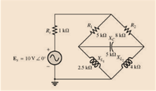
Fig. 18.88
a. Is the bridge balanced?
b. Using mesh analysis, determine the current through the capacitive reactance.
c. Using nodal analysis, determine the voltage across the capacitive reactance.
Expert Solution & Answer
Want to see the full answer?
Check out a sample textbook solution
Students have asked these similar questions
HW4C2
4. Using superposition, find the sinusoidal expression for
the voltage Ve for the network of Fig. 18.112.
12 V
4A 20
FIG. 18.112
5485+19
4. Determine the node voltages, V₁ and V₂,
using nodal analysis.
loA
GA
102
M
482
24a (1)18A
Chapter 18 Solutions
Introductory Circuit Analysis (13th Edition)
Ch. 18 - Discuss, in your own words, the difference between...Ch. 18 - Convert the voltage source in Fig. 18.62 to a...Ch. 18 - Convert the current source in Fig. 18.63 to a...Ch. 18 - Convert the votage source in Fig. 18.64(a) to a...Ch. 18 - Write the mesh equations for the network of Fig....Ch. 18 - Write the mesh equations for the network of Fig....Ch. 18 - Write the mesh equations for the network of Fig....Ch. 18 - Write the mesh equations for the network of Fig....Ch. 18 - Write the mesh equations for the network of Fig....Ch. 18 - Write the mesh equtions for the network of Fig....
Ch. 18 - Write the mesh equations for the network of Fig....Ch. 18 - Using mesh analysis, determine the current IL (in...Ch. 18 - Using mesh analysis, determine the current IL (in...Ch. 18 - Write the mesh equations for the network of Fig....Ch. 18 - Write the mesh equations for the network of...Ch. 18 - Write the mesh equations for the network of Fig....Ch. 18 - Determine the nodal voltages for the network of...Ch. 18 - Determine the nodal voltages for the network of...Ch. 18 - Determine the nodal voltages for the network of...Ch. 18 - Determine the nodal voltages for the network of...Ch. 18 - Determine the nodal voltages for the network of...Ch. 18 - Determine the nodal voltages for the network of...Ch. 18 - Determine the nodal votas for the network of Fig....Ch. 18 - Determine the nodal voltages for the network of...Ch. 18 - Write the nodal equations for the network in Fig....Ch. 18 - Write the nodal equations for the network of Fig....Ch. 18 - Write the nodal equations for the network of Fig....Ch. 18 - Write the nodal equations for the network of Fig....Ch. 18 - For the network of Fig. 18.87, determine the...Ch. 18 - For the bridge network in Fig. 18.88: Fig. 18.88...Ch. 18 - For the bridge network in Fig. 18.89: a. Is the...Ch. 18 - The Hay bridge in Fig. 18.90 is balanced. Using...Ch. 18 - Determine whether the Maxwell bridge in Fig. 18.91...Ch. 18 - Derive the balance equations (18.16) and (18.17)...Ch. 18 - Determine the balance equations for the inductance...Ch. 18 - Using the -YorY-conversion, determine the current...Ch. 18 - Using the -YorY-conversion, determine the current...Ch. 18 - Using the -YorY-conversion, determine the current...Ch. 18 - Using the -YorY-conversion, determine the current...Ch. 18 - Determine the mesh currents for the network of...Ch. 18 - Prob. 41PCh. 18 - Prob. 42PCh. 18 - Prob. 43PCh. 18 - Prob. 44PCh. 18 - Determine the nodal voltages for the network of...Ch. 18 - Determine the nodal voltages for the network of...Ch. 18 - Prob. 47PCh. 18 - Determine the nodal voltages for the network of...Ch. 18 - Determine the nodal voltages for the network of...
Knowledge Booster


Learn more about
Need a deep-dive on the concept behind this application? Look no further. Learn more about this topic, electrical-engineering and related others by exploring similar questions and additional content below.Similar questions
- Use Nodal Analysis to determine I.arrow_forward3. A single-phase 50 Hz generator supplies an inductive load of 5 MW at a power factor of 0-866 lagging by means of an overhead transmission :"line 20 km long. The line resistance and inductance are 0:0195 ohm and 0:63 mH per km The voltage at the receiving end is réquired to be kept.constant at 10 kV. (a) Find the sendingend voltage and voltage regulation of the line.arrow_forwardQuestion 1 A three-phase, 50 Hz overhead short transmission line has a line-to-line voltage of 11V3 kV at the receiving end, a total impedance of 3 + j4 0/phase, and a load of 33 MW with a receiving-end lagging PF of 0.707. a. Calculate the line-to-neutral voltage at the receiving end. b. Calculate the line current. c. Calculate the line-to-neutral at the sending end. d. Calculate the line-to-line voltages at the sending end. e. Calculate the load angle.arrow_forward
- AaBbCcDc AaBbCcDc AaBbC AaBbCc A aB AaBl U - abe x, x I Normal I No Spaci.. Heading 1 Heading 2 Title Subt Font Paragraph Styles Q16. Find out the bus admittance matrix [Ybus] of the power system as shown in Fig.2.Data of the system are given in table-1 FL20, AY2020-2021. Page 3 1: Per unit impedances and line charging for sample power system shown in Fig. 1 Table Bus code i-k Impedance Z Line charging Y ik2 0.01+ 0.0 3 0.0 4 0.25 0.03+ 0.14 1-2 0.03 0.025 0.020 1-3 Fig. 1 3 bus sample power system. 2-3 0.874-j1.71 - 0.39+0.65 -0.19+j0.96 -0.21+j0.77 0.768-j2.95 0.47-j1.91 -0.32+j0.95 -0.16-j0.99 - 0.32+0.95 -0.52+j0.75 -0.188-j0.93 O 0.93-j1.61 0.57-j1.81 -0.32+j0.85 -0.168+j0.96 - 0.36+j0.65 0.56-j1.95 -0.31+j0.92 -0.2+j0.69 -0.31-j0.89 -0.41+j0.92 0.77-j1.85 O None of the above 0.53-i1.91 -0.21+i0.98 sh (U.S.)arrow_forwardUsing admittance parameters determine I0 for the circuit shown belowarrow_forward1. A 3 phase feeder having a resistance of 3 ohms and a reactance of 10ohms supplies a load of 2 MW at 0.85 pf lagging. The receiving end voltage is maintained at 11kV by means of a static condenser drawing 2.1 MVAR from the line. Calculate the sending end voltage and p.f. Also find the voltage regulation and efficiency of the feeder. Assume Delta connected.arrow_forward
- 1, E 48 V RT, GT R₁8k0 For the network above a. Find the total conductance and resistance. units GT = RT= units b. Determine I, and the current through each parallel branch (11 and 12). ls = 1₁ = ¹2= unts units R₂ 24 k units c. True or False, the sum of the brance currents equal the source current xarrow_forward4) The national standard phase sequence in oman is R B Y Select one: True Falsearrow_forwardChopper is feeding R-L load, V=200 V, R= 502, L=5 mH, f=1 kHz, D=0.5, E=0. Calculate: a. Imin & Imax. b. Average value for the load current. c. Time domain equations of load current iL1 (t) & i12 (t) ●arrow_forward
arrow_back_ios
SEE MORE QUESTIONS
arrow_forward_ios
Recommended textbooks for you
 Introductory Circuit Analysis (13th Edition)Electrical EngineeringISBN:9780133923605Author:Robert L. BoylestadPublisher:PEARSON
 Delmar's Standard Textbook Of ElectricityElectrical EngineeringISBN:9781337900348Author:Stephen L. HermanPublisher:Cengage Learning
 Programmable Logic ControllersElectrical EngineeringISBN:9780073373843Author:Frank D. PetruzellaPublisher:McGraw-Hill Education
 Fundamentals of Electric CircuitsElectrical EngineeringISBN:9780078028229Author:Charles K Alexander, Matthew SadikuPublisher:McGraw-Hill Education
 Electric Circuits. (11th Edition)Electrical EngineeringISBN:9780134746968Author:James W. Nilsson, Susan RiedelPublisher:PEARSON
 Engineering ElectromagneticsElectrical EngineeringISBN:9780078028151Author:Hayt, William H. (william Hart), Jr, BUCK, John A.Publisher:Mcgraw-hill Education,
Introductory Circuit Analysis (13th Edition)
Electrical Engineering
ISBN:9780133923605
Author:Robert L. Boylestad
Publisher:PEARSON
Delmar's Standard Textbook Of Electricity
Electrical Engineering
ISBN:9781337900348
Author:Stephen L. Herman
Publisher:Cengage Learning
Programmable Logic Controllers
Electrical Engineering
ISBN:9780073373843
Author:Frank D. Petruzella
Publisher:McGraw-Hill Education
Fundamentals of Electric Circuits
Electrical Engineering
ISBN:9780078028229
Author:Charles K Alexander, Matthew Sadiku
Publisher:McGraw-Hill Education
Electric Circuits. (11th Edition)
Electrical Engineering
ISBN:9780134746968
Author:James W. Nilsson, Susan Riedel
Publisher:PEARSON
Engineering Electromagnetics
Electrical Engineering
ISBN:9780078028151
Author:Hayt, William H. (william Hart), Jr, BUCK, John A.
Publisher:Mcgraw-hill Education,
Current Divider Rule; Author: Neso Academy;https://www.youtube.com/watch?v=hRU1mKWUehY;License: Standard YouTube License, CC-BY