
Statics and Mechanics of Materials (5th Edition)
5th Edition
ISBN: 9780134382593
Author: Russell C. Hibbeler
Publisher: PEARSON
expand_more
expand_more
format_list_bulleted
Videos
Textbook Question
Chapter 16.4, Problem 54P
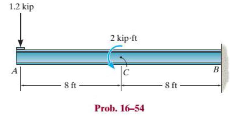
The W8 × 48 cantilevered beam is made of A-36 steel and is subjected to the loading shown. Determine the displacement at its end A.
Expert Solution & Answer
Want to see the full answer?
Check out a sample textbook solution
Students have asked these similar questions
Continuity equation
A
y
x
dx
D
T
معادلة الاستمرارية
Ly
X
Q/Prove that
ди
хе
+ ♥+ ㅇ?
he
me
ze
ོ༞“༠ ?
Q
Derive (continuity equation)?
I want to derive clear mathematics.
motor supplies 200 kW at 6 Hz to flange A of the shaft shown in Figure. Gear B transfers 125 W of power to operating machinery in the factory, and the remaining power in the shaft is mansferred by gear D. Shafts (1) and (2) are solid aluminum (G = 28 GPa) shafts that have the same diameter and an allowable shear stress of t= 40 MPa. Shaft (3) is a solid steel (G = 80 GPa) shaft with an allowable shear stress of t = 55 MPa. Determine:
a) the minimum permissible diameter for aluminum shafts (1) and (2)
b) the minimum permissible diameter for steel shaft (3).
c) the rotation angle of gear D with respect to flange A if the shafts have the minimum permissible diameters as determined in (a) and (b).
Chapter 16 Solutions
Statics and Mechanics of Materials (5th Edition)
Ch. 16.2 - In each ease, determine the internal bending...Ch. 16.2 - Prob. 1FPCh. 16.2 - Determine the slope and deflection of end A of the...Ch. 16.2 - Prob. 3FPCh. 16.2 - Prob. 4FPCh. 16.2 - Determine the maximum deflection of the simply...Ch. 16.2 - Prob. 6FPCh. 16.2 - An L2 steel strap having a thickness of 0.125 in....Ch. 16.2 - The L2 steel blade of the band saw wraps around...Ch. 16.2 - A picture is taken of a man performing a pole...
Ch. 16.2 - Determine the equation of the elastic curve for...Ch. 16.2 - Determine the deflection of end C of the...Ch. 16.2 - Prob. 6PCh. 16.2 - The A-36 steel beam has a depth of 10 in. and is...Ch. 16.2 - Prob. 8PCh. 16.2 - Determine the equations of the elastic curve for...Ch. 16.2 - Determine the equations of the elastic curve using...Ch. 16.2 - Determine the equations of the elastic curve using...Ch. 16.2 - Prob. 12PCh. 16.2 - Determine the maximum deflection of the beam and...Ch. 16.2 - The simply supported shaft has a moment of inertia...Ch. 16.2 - A torque wrench is used to tighten the nut on a...Ch. 16.2 - The pipe can be assumed roller supported at its...Ch. 16.2 - Determine the equations of the elastic curve for...Ch. 16.2 - The bar is supported by a roller constraint at B,...Ch. 16.2 - The bar is supported by a roller constraint at B,...Ch. 16.2 - Determine the equations of the elastic curve using...Ch. 16.2 - Prob. 21PCh. 16.2 - Determine the elastic curve for the cantilevered...Ch. 16.2 - Prob. 23PCh. 16.2 - Prob. 24PCh. 16.2 - The floor beam of the airplane is subjected to the...Ch. 16.2 - Determine the maximum deflection of the simply...Ch. 16.2 - The beam is made of a material having a specific...Ch. 16.2 - Determine the slope at end B and the maximum...Ch. 16.2 - Prob. 29PCh. 16.2 - Determine the equations of the elastic curve using...Ch. 16.3 - The shaft is supported at A by a journal bearing...Ch. 16.3 - The shaft supports the two pulley loads shown....Ch. 16.3 - Prob. 33PCh. 16.3 - Prob. 34PCh. 16.3 - The beam is subjected to the load shown. Determine...Ch. 16.3 - Prob. 36PCh. 16.3 - Determine the equation of the elastic curve and...Ch. 16.3 - Prob. 38PCh. 16.3 - Prob. 39PCh. 16.3 - Determine the slope at A and the deflection of end...Ch. 16.3 - Determine the maximum deflection in region AB of...Ch. 16.3 - Prob. 42PCh. 16.3 - Prob. 43PCh. 16.3 - Prob. 44PCh. 16.4 - The W10 15 cantilevered beam is made of A-36...Ch. 16.4 - The W10 15 cantilevered beam is made of A-36...Ch. 16.4 - The W14 43 simply supported beam is made of A992...Ch. 16.4 - The W14 43 simply supported beam is made of A992...Ch. 16.4 - The W14 43 simply supported beam is made of A-36...Ch. 16.4 - The W14 43 simply supported beam is made of A-36...Ch. 16.4 - The W8 48 cantilevered beam is made of A-36 steel...Ch. 16.4 - The beam supports the loading shown. Code...Ch. 16.4 - Prob. 53PCh. 16.4 - The W8 48 cantilevered beam is made of A-36 steel...Ch. 16.4 - Prob. 55PCh. 16.4 - Prob. 56PCh. 16.4 - Prob. 57PCh. 16.4 - The assembly consists of a cantilevered beam CB...Ch. 16.4 - Prob. 59PCh. 16.4 - Prob. 60PCh. 16.5 - Determine the reactions at the fixed support A and...Ch. 16.5 - Prob. 8FPCh. 16.5 - Determine the reactions at the fixed support A and...Ch. 16.5 - Prob. 10FPCh. 16.5 - Prob. 11FPCh. 16.5 - Prob. 12FPCh. 16.5 - Prob. 61PCh. 16.5 - Determine the reactions at the supports, then draw...Ch. 16.5 - Determine the reactions at the supports, then draw...Ch. 16.5 - Prob. 64PCh. 16.5 - The beam is used to support the 20-kip load....Ch. 16.5 - Prob. 66PCh. 16.5 - Determine the reactions at the supports A and B....Ch. 16.5 - Before the uniform distributed load is applied to...Ch. 16.5 - Prob. 69PCh. 16.5 - Prob. 70PCh. 16.5 - The beam is supported by the bolted supports at...Ch. 16.5 - Prob. 72PCh. 16.5 - Prob. 73PCh. 16 - Prob. 1RPCh. 16 - Draw the bending-moment diagram for the shaft and...Ch. 16 - Prob. 3RPCh. 16 - Determine the equations of the elastic curve for...Ch. 16 - Determine the maximum deflection between the...Ch. 16 - Prob. 6RPCh. 16 - The framework consists of two A-36 steel...Ch. 16 - Prob. 8RPCh. 16 - Using the method of superposition, determine the...
Knowledge Booster


Learn more about
Need a deep-dive on the concept behind this application? Look no further. Learn more about this topic, mechanical-engineering and related others by exploring similar questions and additional content below.Similar questions
- First monthly exam Gas dynamics Third stage Q1/Water at 15° C flow through a 300 mm diameter riveted steel pipe, E-3 mm with a head loss of 6 m in 300 m length. Determine the flow rate in pipe. Use moody chart. Q2/ Assume a car's exhaust system can be approximated as 14 ft long and 0.125 ft-diameter cast-iron pipe ( = 0.00085 ft) with the equivalent of (6) regular 90° flanged elbows (KL = 0.3) and a muffler. The muffler acts as a resistor with a loss coefficient of KL= 8.5. Determine the pressure at the beginning of the exhaust system (pl) if the flowrate is 0.10 cfs, and the exhaust has the same properties as air.(p = 1.74 × 10⁻³ slug/ft³, u= 4.7 x 10⁻⁷ lb.s/ft²) Use moody chart (1) MIDAS Kel=0.3 Q3/Liquid ammonia at -20°C is flowing through a 30 m long section of a 5 mm diameter copper tube(e = 1.5 × 10⁻⁶ m) at a rate of 0.15 kg/s. Determine the pressure drop and the head losses. .μ= 2.36 × 10⁻⁴ kg/m.s)p = 665.1 kg/m³arrow_forward2/Y Y+1 2Cp Q1/ Show that Cda Az x P1 mactual Cdf Af R/T₁ 2pf(P1-P2-zxgxpf) Q2/ A simple jet carburetor has to supply 5 Kg of air per minute. The air is at a pressure of 1.013 bar and a temperature of 27 °C. Calculate the throat diameter of the choke for air flow velocity of 90 m/sec. Take velocity coefficient to be 0.8. Assume isentropic flow and the flow to be compressible. Quiz/ Determine the air-fuel ratio supplied at 5000 m altitude by a carburetor which is adjusted to give an air-fuel ratio of 14:1 at sea level where air temperature is 27 °C and pressure is 1.013 bar. The temperature of air decreases with altitude as given by the expression The air pressure decreases with altitude as per relation h = 19200 log10 (1.013), where P is in bar. State any assumptions made. t = ts P 0.0065harrow_forward36 2) Use the method of MEMBERS to determine the true magnitude and direction of the forces in members1 and 2 of the frame shown below in Fig 3.2. 300lbs/ft member-1 member-2 30° Fig 3.2. https://brightspace.cuny.edu/d21/le/content/433117/viewContent/29873977/Viewarrow_forward
- Can you solve this for me?arrow_forward5670 mm The apartment in the ground floor of three floors building in Fig. in Baghdad city. The details of walls, roof, windows and door are shown. The window is a double glazing and air space thickness is 1.3cm Poorly Fitted-with Storm Sash with wood strip and storm window of 0.6 cm glass thickness. The thickness of door is 2.5 cm. The door is Poor Installation. There are two peoples in each room. The height of room is 280 cm. assume the indoor design conditions are 25°C DBT and 50 RH, and moisture content of 8 gw/kga. The moisture content of outdoor is 10.5 gw/kga. Calculate heat gain for living room : الشقة في الطابق الأرضي من مبنى ثلاثة طوابق في مدينة بغداد يظهر في مخطط الشقة تفاصيل الجدران والسقف والنوافذ والباب. النافذة عبارة عن زجاج مزدوج وسمك الفراغ الهوائي 1.3 سم ضعيف الاحكام مع ساتر حماية مع إطار خشبي والنافذة بسماكة زجاج 0.6 سم سماكة الباب 2.5 سم. الباب هو تركيب ضعيف هناك شخصان في كل غرفة. ارتفاع الغرفة 280 سم. افترض أن ظروف التصميم الداخلي هي DBT25 و R50 ، ومحتوى الرطوبة 8…arrow_forwardHow do i solve this problem?arrow_forward
- Q4/ A compressor is driven motor by mean of a flat belt of thickness 10 mm and a width of 250 mm. The motor pulley is 300 mm diameter and run at 900 rpm and the compressor pulley is 1500 mm diameter. The shaft center distance is 1.5 m. The angle of contact of the smaller pulley is 220° and on the larger pulley is 270°. The coefficient of friction between the belt and the small pulley is 0.3, and between the belt and the large pulley is 0.25. The maximum allowable belt stress is 2 MPa and the belt density is 970 kg/m³. (a) What is the power capacity of the drive and (b) If the small pulley replaced by V-grooved pulley of diameter 300 mm, grooved angle of 34° and the coefficient of friction between belt and grooved pulley is 0.35. What will be the power capacity in this case, assuming that the diameter of the large pulley remain the same of 1500 mm.arrow_forwardYou are tasked with designing a power drive system to transmit power between a motor and a conveyor belt in a manufacturing facility as illustrated in figure. The design must ensure efficient power transmission, reliability, and safety. Given the following specifications and constraints, design drive system for this application: Specifications: Motor Power: The electric motor provides 10 kW of power at 1,500 RPM. Output Speed: The output shaft should rotate at 150 rpm. Design Decisions: Transmission ratio: Determine the necessary drive ratio for the system. Shaft Diameter: Design the shafts for both the motor and the conveyor end. Material Selection: Choose appropriate materials for the gears, shafts. Bearings: Select suitable rolling element bearings. Constraints: Space Limitation: The available space for the gear drive system is limited to a 1-meter-long section. Attribute 4 of CEP Depth of knowledge required Fundamentals-based, first principles analytical approach…arrow_forward- | العنوان In non-continuous dieless drawing process for copper tube as shown in Fig. (1), take the following data: Do-20mm, to=3mm, D=12mm, ti/to=0.6 and v.-15mm/s. Calculate: (1) area reduction RA, (2) drawing velocity v. Knowing that: ti: final thickness V. Fig. (1) ofthrearrow_forward
- A direct extrusion operation produces the cross section shown in Fig. (2) from an aluminum billet whose diameter 160 mm and length - 700 mm. Determine the length of the extruded section at the end of the operation if the die angle -14° 60 X Fig. (2) Note: all dimensions in mm.arrow_forwardFor hot rolling processes, show that the average strain rate can be given as: = (1+5)√RdIn(+1)arrow_forward: +0 usão العنوان on to A vertical true centrifugal casting process is used to produce bushings that are 250 mm long and 200 mm in outside diameter. If the rotational speed during solidification is 500 rev/min, determine the inside radii at the top and bottom of the bushing if R-2R. Take: -9.81 mis ۲/۱ ostrararrow_forward
arrow_back_ios
SEE MORE QUESTIONS
arrow_forward_ios
Recommended textbooks for you
 Elements Of ElectromagneticsMechanical EngineeringISBN:9780190698614Author:Sadiku, Matthew N. O.Publisher:Oxford University Press
 Mechanics of Materials (10th Edition)Mechanical EngineeringISBN:9780134319650Author:Russell C. HibbelerPublisher:PEARSON
 Thermodynamics: An Engineering ApproachMechanical EngineeringISBN:9781259822674Author:Yunus A. Cengel Dr., Michael A. BolesPublisher:McGraw-Hill Education
 Control Systems EngineeringMechanical EngineeringISBN:9781118170519Author:Norman S. NisePublisher:WILEY
 Mechanics of Materials (MindTap Course List)Mechanical EngineeringISBN:9781337093347Author:Barry J. Goodno, James M. GerePublisher:Cengage Learning
 Engineering Mechanics: StaticsMechanical EngineeringISBN:9781118807330Author:James L. Meriam, L. G. Kraige, J. N. BoltonPublisher:WILEY
Elements Of Electromagnetics
Mechanical Engineering
ISBN:9780190698614
Author:Sadiku, Matthew N. O.
Publisher:Oxford University Press
Mechanics of Materials (10th Edition)
Mechanical Engineering
ISBN:9780134319650
Author:Russell C. Hibbeler
Publisher:PEARSON
Thermodynamics: An Engineering Approach
Mechanical Engineering
ISBN:9781259822674
Author:Yunus A. Cengel Dr., Michael A. Boles
Publisher:McGraw-Hill Education
Control Systems Engineering
Mechanical Engineering
ISBN:9781118170519
Author:Norman S. Nise
Publisher:WILEY
Mechanics of Materials (MindTap Course List)
Mechanical Engineering
ISBN:9781337093347
Author:Barry J. Goodno, James M. Gere
Publisher:Cengage Learning
Engineering Mechanics: Statics
Mechanical Engineering
ISBN:9781118807330
Author:James L. Meriam, L. G. Kraige, J. N. Bolton
Publisher:WILEY
Mechanics of Materials Lecture: Beam Design; Author: UWMC Engineering;https://www.youtube.com/watch?v=-wVs5pvQPm4;License: Standard Youtube License