
Statics and Mechanics of Materials (5th Edition)
5th Edition
ISBN: 9780134382593
Author: Russell C. Hibbeler
Publisher: PEARSON
expand_more
expand_more
format_list_bulleted
Concept explainers
Videos
Textbook Question
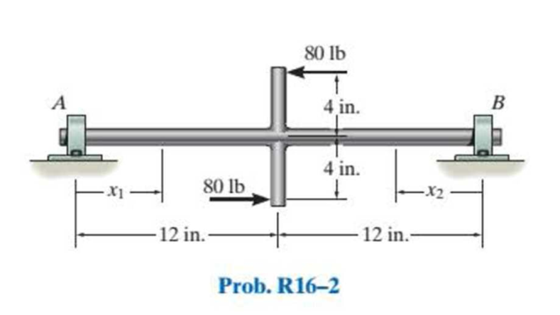
Chapter 16, Problem 2RP
Draw the bending-moment diagram for the shaft and then, from this diagram, sketch the deflection or elastic curve for the shaft’s centerline. Determine the equations of the elastic curve using the coordinates x1 and x2. Use the method of integration. EI is constant.
Expert Solution & Answer
Want to see the full answer?
Check out a sample textbook solution
Students have asked these similar questions
H.W 5.4
Calculate the load that will make point A move to the left by 6mm, E-228GPa. The diameters
of the rods are as shown in fig. below.
2P-
PA
50mm
B
200mm
2P
0.9m
1.3m
d₁
=
=
Two solid cylindrical road AB and
BC are welded together at B and
loaded as shown. Knowing that
30mm (for AB) and d₂
50mm (for BC), find the average
normal stress in each road and the
total deformation of road AB and
BC. E=220GPa
H.W 5.3
60kN
A
For the previous example calculate the
value of force P so that the point A will not
move, and what is the total length of road
AB at that force?
P◄
A
125kN
125kN
0.9m
125kN
125kN
0.9m
B
B
1.3m
1.3m
Class:
B
Calculate the load that will make point A move to the left by 6mm, E-228GPa
The cross sections of the rods are as shown in fig. below.
183
P-
Solution
1.418mm
200mm
80mm
3P-
18.3
A
080mm
B
200mm
3P-
0.9m
إعدادات العرض
1.3m
4.061mm
Chapter 16 Solutions
Statics and Mechanics of Materials (5th Edition)
Ch. 16.2 - In each ease, determine the internal bending...Ch. 16.2 - Prob. 1FPCh. 16.2 - Determine the slope and deflection of end A of the...Ch. 16.2 - Prob. 3FPCh. 16.2 - Prob. 4FPCh. 16.2 - Determine the maximum deflection of the simply...Ch. 16.2 - Prob. 6FPCh. 16.2 - An L2 steel strap having a thickness of 0.125 in....Ch. 16.2 - The L2 steel blade of the band saw wraps around...Ch. 16.2 - A picture is taken of a man performing a pole...
Ch. 16.2 - Determine the equation of the elastic curve for...Ch. 16.2 - Determine the deflection of end C of the...Ch. 16.2 - Prob. 6PCh. 16.2 - The A-36 steel beam has a depth of 10 in. and is...Ch. 16.2 - Prob. 8PCh. 16.2 - Determine the equations of the elastic curve for...Ch. 16.2 - Determine the equations of the elastic curve using...Ch. 16.2 - Determine the equations of the elastic curve using...Ch. 16.2 - Prob. 12PCh. 16.2 - Determine the maximum deflection of the beam and...Ch. 16.2 - The simply supported shaft has a moment of inertia...Ch. 16.2 - A torque wrench is used to tighten the nut on a...Ch. 16.2 - The pipe can be assumed roller supported at its...Ch. 16.2 - Determine the equations of the elastic curve for...Ch. 16.2 - The bar is supported by a roller constraint at B,...Ch. 16.2 - The bar is supported by a roller constraint at B,...Ch. 16.2 - Determine the equations of the elastic curve using...Ch. 16.2 - Prob. 21PCh. 16.2 - Determine the elastic curve for the cantilevered...Ch. 16.2 - Prob. 23PCh. 16.2 - Prob. 24PCh. 16.2 - The floor beam of the airplane is subjected to the...Ch. 16.2 - Determine the maximum deflection of the simply...Ch. 16.2 - The beam is made of a material having a specific...Ch. 16.2 - Determine the slope at end B and the maximum...Ch. 16.2 - Prob. 29PCh. 16.2 - Determine the equations of the elastic curve using...Ch. 16.3 - The shaft is supported at A by a journal bearing...Ch. 16.3 - The shaft supports the two pulley loads shown....Ch. 16.3 - Prob. 33PCh. 16.3 - Prob. 34PCh. 16.3 - The beam is subjected to the load shown. Determine...Ch. 16.3 - Prob. 36PCh. 16.3 - Determine the equation of the elastic curve and...Ch. 16.3 - Prob. 38PCh. 16.3 - Prob. 39PCh. 16.3 - Determine the slope at A and the deflection of end...Ch. 16.3 - Determine the maximum deflection in region AB of...Ch. 16.3 - Prob. 42PCh. 16.3 - Prob. 43PCh. 16.3 - Prob. 44PCh. 16.4 - The W10 15 cantilevered beam is made of A-36...Ch. 16.4 - The W10 15 cantilevered beam is made of A-36...Ch. 16.4 - The W14 43 simply supported beam is made of A992...Ch. 16.4 - The W14 43 simply supported beam is made of A992...Ch. 16.4 - The W14 43 simply supported beam is made of A-36...Ch. 16.4 - The W14 43 simply supported beam is made of A-36...Ch. 16.4 - The W8 48 cantilevered beam is made of A-36 steel...Ch. 16.4 - The beam supports the loading shown. Code...Ch. 16.4 - Prob. 53PCh. 16.4 - The W8 48 cantilevered beam is made of A-36 steel...Ch. 16.4 - Prob. 55PCh. 16.4 - Prob. 56PCh. 16.4 - Prob. 57PCh. 16.4 - The assembly consists of a cantilevered beam CB...Ch. 16.4 - Prob. 59PCh. 16.4 - Prob. 60PCh. 16.5 - Determine the reactions at the fixed support A and...Ch. 16.5 - Prob. 8FPCh. 16.5 - Determine the reactions at the fixed support A and...Ch. 16.5 - Prob. 10FPCh. 16.5 - Prob. 11FPCh. 16.5 - Prob. 12FPCh. 16.5 - Prob. 61PCh. 16.5 - Determine the reactions at the supports, then draw...Ch. 16.5 - Determine the reactions at the supports, then draw...Ch. 16.5 - Prob. 64PCh. 16.5 - The beam is used to support the 20-kip load....Ch. 16.5 - Prob. 66PCh. 16.5 - Determine the reactions at the supports A and B....Ch. 16.5 - Before the uniform distributed load is applied to...Ch. 16.5 - Prob. 69PCh. 16.5 - Prob. 70PCh. 16.5 - The beam is supported by the bolted supports at...Ch. 16.5 - Prob. 72PCh. 16.5 - Prob. 73PCh. 16 - Prob. 1RPCh. 16 - Draw the bending-moment diagram for the shaft and...Ch. 16 - Prob. 3RPCh. 16 - Determine the equations of the elastic curve for...Ch. 16 - Determine the maximum deflection between the...Ch. 16 - Prob. 6RPCh. 16 - The framework consists of two A-36 steel...Ch. 16 - Prob. 8RPCh. 16 - Using the method of superposition, determine the...
Knowledge Booster


Learn more about
Need a deep-dive on the concept behind this application? Look no further. Learn more about this topic, mechanical-engineering and related others by exploring similar questions and additional content below.Similar questions
- H.W6 Determine the largest weight W that can be supported by two wires shown in Fig. P109. The stress in either wire is not to exceed 30 ksi. The cross- sectional areas of wires AB and AC are 0.4 in2 and 0.5 in2, respectively. 50° 30° Warrow_forwardFind equation of motion and natural frequency for the system shown in fig. by energy method. H.W2// For the system Fig below find 1-F.B.D 2-Eq.of motion 8wn 4-0 (5) m. Jo marrow_forward2. Read the following Vernier caliper measurements. (The scales have been enlarged for easier reading.) The Vernier caliper is calibrated in metric units. (a) 0 1 2 3 4 5 سلسلسله (b) 1 2 3 4 5 6 سلسل (c) 1 23456 (d) 1 2 3 4 5 6 سلسلسarrow_forward
- Explain why on the interval 0<x<1000 mm and 1000<x<2000mm, Mt is equal to positive 160 Nm, but at x= 0mm and x=1000mm Mt is equal to -160 Nm (negative value!). What is the reason for the sign change of Mt?arrow_forward20 3. 2-233 2520 Тр Gears 1079 A pair of helical gears consist of a 20 teeth pinion meshing with a 100 teeth gear. The pinion rotates at Ta 720 r.p.m. The normal pressure angle is 20° while the helix angle is 25°. The face width is 40 mm and the normal module is 4 mm. The pinion as well as gear are made of steel having ultimate strength of 600 MPa and heat treated to a surface hardness of 300 B.H.N. The service factor and factor of safety are 1.5 and 2 respectively. Assume that the velocity factor accounts for the dynamic load and calculate the power transmitting capacity of the gears. [Ans. 8.6 kWarrow_forward4. A single stage helical gear reducer is to receive power from a 1440 r.p.m., 25 kW induction motor. The gear tooth profile is involute full depth with 20° normal pressure angle. The helix angle is 23°, number of teeth on pinion is 20 and the gear ratio is 3. Both the gears are made of steel with allowable beam stress of 90 MPa and hardness 250 B.H.N. (a) Design the gears for 20% overload carrying capacity from standpoint of bending strength and wear, (b) If the incremental dynamic load of 8 kN is estimated in tangential plane, what will be the safe power transmitted by the pair at the same speed?arrow_forward
- Determine the stress in each section of the bar shown in Fig. when subjected to an axial tensile load shown in Fig. The central section is 30 mm hollow square cross- section; the other portions are of circular section, their diameters being indicated What will be the total deformation of the bar? For the bar material E = 210GPa. 20mi О 30mm 30mmm 2.6 15mm 30kN 1 2 10kN - 20kN 3 -329 91mm 100mm 371mmarrow_forwardCalculate the load that will make point A move to the left by 6mm, E=228GPa. The diameters of the rods are as shown in fig. below. 2P- PA 80mm B 200mm 2P 0.9m 1.3m.arrow_forwardIf the rods are made from a square section with the dimension as shown. Calculate the load that will make point A move to the left by 6mm, E=228GPa. 2P- P A 80mm B 200mm 2P 0.9m 1.3marrow_forward
- 3. 9. 10. The centrifugal tension in belts (a) increases power transmitted (b) decreases power transmitted (c) have no effect on the power transmitted (d) increases power transmitted upto a certain speed and then decreases When the belt is stationary, it is subjected to some tension, known as initial tension. The value of this tension is equal to the (a) tension in the tight side of the belt (b) tension in the slack side of the belt (c) sum of the tensions in the tight side and slack side of the belt (d) average tension of the tight side and slack side of the belt The relation between the pitch of the chain (p) and pitch circle diameter of the sprocket (d) is given by 60° (a) p=d sin (c) p=d sin (120° T where T Number of teeth on the sprocket. 90° (b) p=d sin T 180° (d) p=d sin Tarrow_forwardOBJECTIVE TYPE QUESTIONS 1. The maximum fluctuation of energy is the 2. (a) sum of maximum and minimum energies (b) difference between the maximum and minimum energies (c) ratio of the maximum energy and minimum energy (d) ratio of the mean resisting torque to the work done per cycle In a turning moment diagram, the variations of energy above and below the mean resisting torque line is called (a) fluctuation of energy (b) maximum fluctuation of energy (c) coefficient of fluctuation of energy (d) none of the above Chapter 16: Turning Moment Diagrams and Flywheel 611 The ratio of the maximum fluctuation of speed to the mean speed is called 3. (a) fluctuation of speed (c) coefficient of fluctuation of speed 4. (b) maximum fluctuation of speed (a) none of these The ratio of the maximum fluctuation of energy to the.......... is called coefficient of fluctuation of energy. (a) minimum fluctuation of energy (b) work done per cycle The maximum fluctuation of energy in a flywheel is equal to 5.…arrow_forwardOBJECTIVE TYPE QUESTIONS 1. The velocity ratio of two pulleys connected by an open belt or crossed belt is 2. (a) directly proportional to their diameters (b) inversely proportional to their diameters (c) directly proportional to the square of their diameters (d) inversely proportional to the square of their diameters Two pulleys of diameters d, and d, and at distance x apart are connected by means of an open belt drive. The length of the belt is (a)(d+d₁)+2x+ (d₁+d₂)² 4x (b)(d₁-d₂)+2x+ (d₁-d₂)² 4x (c)(d₁+d₂)+ +2x+ (d₁-d₂)² 4x (d)(d-d₂)+2x+ (d₁ +d₂)² 4x 3. In a cone pulley, if the sum of radii of the pulleys on the driving and driven shafts is constant, then (a) open belt drive is recommended (b) cross belt drive is recommended (c) both open belt drive and cross belt drive are recommended (d) the drive is recommended depending upon the torque transmitted Due to slip of the belt, the velocity ratio of the belt drive 4. (a) decreases 5. (b) increases (c) does not change When two pulleys…arrow_forward
arrow_back_ios
SEE MORE QUESTIONS
arrow_forward_ios
Recommended textbooks for you
 Mechanics of Materials (MindTap Course List)Mechanical EngineeringISBN:9781337093347Author:Barry J. Goodno, James M. GerePublisher:Cengage Learning
Mechanics of Materials (MindTap Course List)
Mechanical Engineering
ISBN:9781337093347
Author:Barry J. Goodno, James M. Gere
Publisher:Cengage Learning
Understanding Shear Force and Bending Moment Diagrams; Author: The Efficient Engineer;https://www.youtube.com/watch?v=C-FEVzI8oe8;License: Standard YouTube License, CC-BY
Bending Stress; Author: moodlemech;https://www.youtube.com/watch?v=9QIqewkE6xM;License: Standard Youtube License