
Statics and Mechanics of Materials (5th Edition)
5th Edition
ISBN: 9780134382593
Author: Russell C. Hibbeler
Publisher: PEARSON
expand_more
expand_more
format_list_bulleted
Concept explainers
Videos
Textbook Question
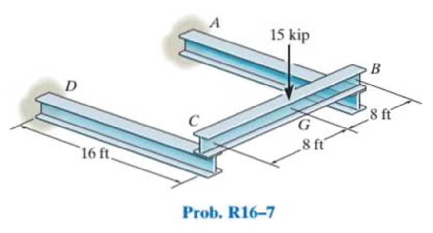
Chapter 16, Problem 7RP
The framework consists of two A-36 steel cantilevered beams CD and BA and a simply supported beam CB. If each beam is made of steel and has a moment of inertia about its principal axis of Ix = 118 in4, determine the deflection at the center G of beam CB. Use the method of superposition.
Expert Solution & Answer
Want to see the full answer?
Check out a sample textbook solution
Students have asked these similar questions
Find the torsion constant of the following beam cross section.
Determine the second moment of area (Iyy) about the centroidal y-axis for a solid homogeneous beam section where the dimensions are b = 125 mm and d = 275 mm.
Give your answer in m4 to 2 significant figures.
The simply supported shaft has a moment of inertia of 2I for region BC and a moment of inertia I for regions AB and CD. Determine the maximum deflection of the shaft due to the load P.
Chapter 16 Solutions
Statics and Mechanics of Materials (5th Edition)
Ch. 16.2 - In each ease, determine the internal bending...Ch. 16.2 - Prob. 1FPCh. 16.2 - Determine the slope and deflection of end A of the...Ch. 16.2 - Prob. 3FPCh. 16.2 - Prob. 4FPCh. 16.2 - Determine the maximum deflection of the simply...Ch. 16.2 - Prob. 6FPCh. 16.2 - An L2 steel strap having a thickness of 0.125 in....Ch. 16.2 - The L2 steel blade of the band saw wraps around...Ch. 16.2 - A picture is taken of a man performing a pole...
Ch. 16.2 - Determine the equation of the elastic curve for...Ch. 16.2 - Determine the deflection of end C of the...Ch. 16.2 - Prob. 6PCh. 16.2 - The A-36 steel beam has a depth of 10 in. and is...Ch. 16.2 - Prob. 8PCh. 16.2 - Determine the equations of the elastic curve for...Ch. 16.2 - Determine the equations of the elastic curve using...Ch. 16.2 - Determine the equations of the elastic curve using...Ch. 16.2 - Prob. 12PCh. 16.2 - Determine the maximum deflection of the beam and...Ch. 16.2 - The simply supported shaft has a moment of inertia...Ch. 16.2 - A torque wrench is used to tighten the nut on a...Ch. 16.2 - The pipe can be assumed roller supported at its...Ch. 16.2 - Determine the equations of the elastic curve for...Ch. 16.2 - The bar is supported by a roller constraint at B,...Ch. 16.2 - The bar is supported by a roller constraint at B,...Ch. 16.2 - Determine the equations of the elastic curve using...Ch. 16.2 - Prob. 21PCh. 16.2 - Determine the elastic curve for the cantilevered...Ch. 16.2 - Prob. 23PCh. 16.2 - Prob. 24PCh. 16.2 - The floor beam of the airplane is subjected to the...Ch. 16.2 - Determine the maximum deflection of the simply...Ch. 16.2 - The beam is made of a material having a specific...Ch. 16.2 - Determine the slope at end B and the maximum...Ch. 16.2 - Prob. 29PCh. 16.2 - Determine the equations of the elastic curve using...Ch. 16.3 - The shaft is supported at A by a journal bearing...Ch. 16.3 - The shaft supports the two pulley loads shown....Ch. 16.3 - Prob. 33PCh. 16.3 - Prob. 34PCh. 16.3 - The beam is subjected to the load shown. Determine...Ch. 16.3 - Prob. 36PCh. 16.3 - Determine the equation of the elastic curve and...Ch. 16.3 - Prob. 38PCh. 16.3 - Prob. 39PCh. 16.3 - Determine the slope at A and the deflection of end...Ch. 16.3 - Determine the maximum deflection in region AB of...Ch. 16.3 - Prob. 42PCh. 16.3 - Prob. 43PCh. 16.3 - Prob. 44PCh. 16.4 - The W10 15 cantilevered beam is made of A-36...Ch. 16.4 - The W10 15 cantilevered beam is made of A-36...Ch. 16.4 - The W14 43 simply supported beam is made of A992...Ch. 16.4 - The W14 43 simply supported beam is made of A992...Ch. 16.4 - The W14 43 simply supported beam is made of A-36...Ch. 16.4 - The W14 43 simply supported beam is made of A-36...Ch. 16.4 - The W8 48 cantilevered beam is made of A-36 steel...Ch. 16.4 - The beam supports the loading shown. Code...Ch. 16.4 - Prob. 53PCh. 16.4 - The W8 48 cantilevered beam is made of A-36 steel...Ch. 16.4 - Prob. 55PCh. 16.4 - Prob. 56PCh. 16.4 - Prob. 57PCh. 16.4 - The assembly consists of a cantilevered beam CB...Ch. 16.4 - Prob. 59PCh. 16.4 - Prob. 60PCh. 16.5 - Determine the reactions at the fixed support A and...Ch. 16.5 - Prob. 8FPCh. 16.5 - Determine the reactions at the fixed support A and...Ch. 16.5 - Prob. 10FPCh. 16.5 - Prob. 11FPCh. 16.5 - Prob. 12FPCh. 16.5 - Prob. 61PCh. 16.5 - Determine the reactions at the supports, then draw...Ch. 16.5 - Determine the reactions at the supports, then draw...Ch. 16.5 - Prob. 64PCh. 16.5 - The beam is used to support the 20-kip load....Ch. 16.5 - Prob. 66PCh. 16.5 - Determine the reactions at the supports A and B....Ch. 16.5 - Before the uniform distributed load is applied to...Ch. 16.5 - Prob. 69PCh. 16.5 - Prob. 70PCh. 16.5 - The beam is supported by the bolted supports at...Ch. 16.5 - Prob. 72PCh. 16.5 - Prob. 73PCh. 16 - Prob. 1RPCh. 16 - Draw the bending-moment diagram for the shaft and...Ch. 16 - Prob. 3RPCh. 16 - Determine the equations of the elastic curve for...Ch. 16 - Determine the maximum deflection between the...Ch. 16 - Prob. 6RPCh. 16 - The framework consists of two A-36 steel...Ch. 16 - Prob. 8RPCh. 16 - Using the method of superposition, determine the...
Knowledge Booster


Learn more about
Need a deep-dive on the concept behind this application? Look no further. Learn more about this topic, mechanical-engineering and related others by exploring similar questions and additional content below.Similar questions
- Determine the second moment of area (lyy) about the centroidal y-axis for a solid homogeneous beam section where the dimensio = 125 mm and d = 275 mm. Give your answer in m4 to 2 significant figures. Ixarrow_forward1. For a simple supported beam with a bending moment diagram shown, determine the following a. Area moment of inertia of the given cross section b. Maximum tensile flexural stress and its location c. Maximum compressive flexural stresses and its location The beam has the triangular section shown: The beam has the triangular section shown. 200 mm 676 E M (Nm) 300 mm - 1200 - 1560 X-sectionarrow_forwardThe steel beam has a fixed support at A and a redundant hanger at B. The hanger rod has a cross sectional area of 3 in2. The member A-B has a moment of inertia I=300 in4. Determine: If the hanger were not attached at B, what would be the deflection at point B (E=29000 ksi)? With the hanger attached at B, determine the force carried in the rod BC. The stress carried in the rod BC. The reactions in the fixed support at A.arrow_forward
- The simply supported shaft has a moment of inertia of 2I for region BC and a moment of inertia I for regions AB and CD. Determine the maximum deflection of the shaft due to the load P. The modulus of elasticity is E.arrow_forwarddetermine the deflection at B in mm using Conjugate Beam Method. Consider 150 mm x 200 (b x h) mm section and E=80 GPa. Enter the absolute value only and round off your answer to 3 decimal places Answer asap. I ratearrow_forwardThe simply supported beam loaded as shown. The length of the beam is 6 m, a = 4 m, the load P = 4000 N, and /= 6000 cm4. Determine the deflection at the center of the beam. Use E = 200 GPą. Use moment by parts. Y x Marrow_forward
- 1. For a simple supported beam with a bending moment diagram shown, determine the following a. Area moment of inertia of the given cross section b. Maximum tensile flexural stress and its location c. Maximum compressive flexural stresses and its location The beam has the triangular section shown: The beam has the triangular section shown. 200 mm 676 D E A M (Nm) B 300 mm - 1200 - 1560 X-sectionarrow_forward2. The steel beam ABCD shown is simply supported at A and supported at B and D by steel cables, each having an effective diameter of 0.5 in. The moment of inertia of the beam is I = 1.2 inª. A force of 5 kips is applied at point C. Determine the deflections of B, C, and D using Superposition method. A 16 in E B 16 in C 5 kips 16 in F D 38 inarrow_forwardUse the principle of superposition, determine the midspan deflection of the beam shown below if E = 10 GPa and I = 20 x 106 mm4. 1 m 2 KN 1 kN/m 4 marrow_forward
- 1. The figure shows Beam Diagram 3 provided by CISC Handbook of Steel Construction, where W=total applied load in kN. (1) using 4th-order differential equation to obtain the deflection equation y (i.e., Ar) for interval 0arrow_forwardFor the steel cantilevered beam shown, determine the minimum moment of inertia of the structural tee section, Imin if the deflection at the free end is limited to 1.2 in. -L2 Given: .L=19.6 ft • L₂ = 6.6 ft F = 1200 lb • q = 1.05 kip/ft Imin=-512.6 79 - ¹/2 |F L +4₂+ L2 H q aarrow_forwardDetermine the smallest moment of inertia I required for the beam shown, so that its maximum deflec- tion does not exceed the limit of 1/360 of the span length (i.e., Amax < L/360). Use the method of virtual work. 50 kN 100 kN 400 C kN . mA В 6 m 6 m -L = 12 m El = constant E = 200 GPa %3Darrow_forwardarrow_back_iosSEE MORE QUESTIONSarrow_forward_ios
Recommended textbooks for you
 Elements Of ElectromagneticsMechanical EngineeringISBN:9780190698614Author:Sadiku, Matthew N. O.Publisher:Oxford University Press
 Mechanics of Materials (10th Edition)Mechanical EngineeringISBN:9780134319650Author:Russell C. HibbelerPublisher:PEARSON
 Thermodynamics: An Engineering ApproachMechanical EngineeringISBN:9781259822674Author:Yunus A. Cengel Dr., Michael A. BolesPublisher:McGraw-Hill Education
 Control Systems EngineeringMechanical EngineeringISBN:9781118170519Author:Norman S. NisePublisher:WILEY
 Mechanics of Materials (MindTap Course List)Mechanical EngineeringISBN:9781337093347Author:Barry J. Goodno, James M. GerePublisher:Cengage Learning
 Engineering Mechanics: StaticsMechanical EngineeringISBN:9781118807330Author:James L. Meriam, L. G. Kraige, J. N. BoltonPublisher:WILEY
Elements Of Electromagnetics
Mechanical Engineering
ISBN:9780190698614
Author:Sadiku, Matthew N. O.
Publisher:Oxford University Press
Mechanics of Materials (10th Edition)
Mechanical Engineering
ISBN:9780134319650
Author:Russell C. Hibbeler
Publisher:PEARSON
Thermodynamics: An Engineering Approach
Mechanical Engineering
ISBN:9781259822674
Author:Yunus A. Cengel Dr., Michael A. Boles
Publisher:McGraw-Hill Education
Control Systems Engineering
Mechanical Engineering
ISBN:9781118170519
Author:Norman S. Nise
Publisher:WILEY
Mechanics of Materials (MindTap Course List)
Mechanical Engineering
ISBN:9781337093347
Author:Barry J. Goodno, James M. Gere
Publisher:Cengage Learning
Engineering Mechanics: Statics
Mechanical Engineering
ISBN:9781118807330
Author:James L. Meriam, L. G. Kraige, J. N. Bolton
Publisher:WILEY
Solids: Lesson 53 - Slope and Deflection of Beams Intro; Author: Jeff Hanson;https://www.youtube.com/watch?v=I7lTq68JRmY;License: Standard YouTube License, CC-BY