
Statics and Mechanics of Materials (5th Edition)
5th Edition
ISBN: 9780134382593
Author: Russell C. Hibbeler
Publisher: PEARSON
expand_more
expand_more
format_list_bulleted
Concept explainers
Videos
Textbook Question
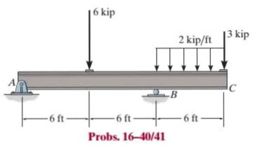
Chapter 16.3, Problem 41P
Determine the maximum deflection in region AB of the overhang beam. Take E = 29(103) ksi and I = 204 in4.
Expert Solution & Answer
Want to see the full answer?
Check out a sample textbook solution
Students have asked these similar questions
Determine the maximum deflection of the cantilevered beam. The beam is made of material having an E=200GPaE=200GPa and I=63(106)mm6I=63(106)mm4 . (Figure 1)
note the image is wrong, must be I=63(106)mm^4
determine the deflection at B in mm using Conjugate Beam Method. Consider 150 mm x 200 (b x h) mm section and E=80 GPa. Enter the absolute value only and round off your answer to 3 decimal places
Answer asap. I rate
2. Using the conjugate beam method, determine the maximum deflection of
the beam. Use E = 10,000 ksi and I = 500 in4.
30 k
A
B
-14 ft-
-7 ft-
Chapter 16 Solutions
Statics and Mechanics of Materials (5th Edition)
Ch. 16.2 - In each ease, determine the internal bending...Ch. 16.2 - Prob. 1FPCh. 16.2 - Determine the slope and deflection of end A of the...Ch. 16.2 - Prob. 3FPCh. 16.2 - Prob. 4FPCh. 16.2 - Determine the maximum deflection of the simply...Ch. 16.2 - Prob. 6FPCh. 16.2 - An L2 steel strap having a thickness of 0.125 in....Ch. 16.2 - The L2 steel blade of the band saw wraps around...Ch. 16.2 - A picture is taken of a man performing a pole...
Ch. 16.2 - Determine the equation of the elastic curve for...Ch. 16.2 - Determine the deflection of end C of the...Ch. 16.2 - Prob. 6PCh. 16.2 - The A-36 steel beam has a depth of 10 in. and is...Ch. 16.2 - Prob. 8PCh. 16.2 - Determine the equations of the elastic curve for...Ch. 16.2 - Determine the equations of the elastic curve using...Ch. 16.2 - Determine the equations of the elastic curve using...Ch. 16.2 - Prob. 12PCh. 16.2 - Determine the maximum deflection of the beam and...Ch. 16.2 - The simply supported shaft has a moment of inertia...Ch. 16.2 - A torque wrench is used to tighten the nut on a...Ch. 16.2 - The pipe can be assumed roller supported at its...Ch. 16.2 - Determine the equations of the elastic curve for...Ch. 16.2 - The bar is supported by a roller constraint at B,...Ch. 16.2 - The bar is supported by a roller constraint at B,...Ch. 16.2 - Determine the equations of the elastic curve using...Ch. 16.2 - Prob. 21PCh. 16.2 - Determine the elastic curve for the cantilevered...Ch. 16.2 - Prob. 23PCh. 16.2 - Prob. 24PCh. 16.2 - The floor beam of the airplane is subjected to the...Ch. 16.2 - Determine the maximum deflection of the simply...Ch. 16.2 - The beam is made of a material having a specific...Ch. 16.2 - Determine the slope at end B and the maximum...Ch. 16.2 - Prob. 29PCh. 16.2 - Determine the equations of the elastic curve using...Ch. 16.3 - The shaft is supported at A by a journal bearing...Ch. 16.3 - The shaft supports the two pulley loads shown....Ch. 16.3 - Prob. 33PCh. 16.3 - Prob. 34PCh. 16.3 - The beam is subjected to the load shown. Determine...Ch. 16.3 - Prob. 36PCh. 16.3 - Determine the equation of the elastic curve and...Ch. 16.3 - Prob. 38PCh. 16.3 - Prob. 39PCh. 16.3 - Determine the slope at A and the deflection of end...Ch. 16.3 - Determine the maximum deflection in region AB of...Ch. 16.3 - Prob. 42PCh. 16.3 - Prob. 43PCh. 16.3 - Prob. 44PCh. 16.4 - The W10 15 cantilevered beam is made of A-36...Ch. 16.4 - The W10 15 cantilevered beam is made of A-36...Ch. 16.4 - The W14 43 simply supported beam is made of A992...Ch. 16.4 - The W14 43 simply supported beam is made of A992...Ch. 16.4 - The W14 43 simply supported beam is made of A-36...Ch. 16.4 - The W14 43 simply supported beam is made of A-36...Ch. 16.4 - The W8 48 cantilevered beam is made of A-36 steel...Ch. 16.4 - The beam supports the loading shown. Code...Ch. 16.4 - Prob. 53PCh. 16.4 - The W8 48 cantilevered beam is made of A-36 steel...Ch. 16.4 - Prob. 55PCh. 16.4 - Prob. 56PCh. 16.4 - Prob. 57PCh. 16.4 - The assembly consists of a cantilevered beam CB...Ch. 16.4 - Prob. 59PCh. 16.4 - Prob. 60PCh. 16.5 - Determine the reactions at the fixed support A and...Ch. 16.5 - Prob. 8FPCh. 16.5 - Determine the reactions at the fixed support A and...Ch. 16.5 - Prob. 10FPCh. 16.5 - Prob. 11FPCh. 16.5 - Prob. 12FPCh. 16.5 - Prob. 61PCh. 16.5 - Determine the reactions at the supports, then draw...Ch. 16.5 - Determine the reactions at the supports, then draw...Ch. 16.5 - Prob. 64PCh. 16.5 - The beam is used to support the 20-kip load....Ch. 16.5 - Prob. 66PCh. 16.5 - Determine the reactions at the supports A and B....Ch. 16.5 - Before the uniform distributed load is applied to...Ch. 16.5 - Prob. 69PCh. 16.5 - Prob. 70PCh. 16.5 - The beam is supported by the bolted supports at...Ch. 16.5 - Prob. 72PCh. 16.5 - Prob. 73PCh. 16 - Prob. 1RPCh. 16 - Draw the bending-moment diagram for the shaft and...Ch. 16 - Prob. 3RPCh. 16 - Determine the equations of the elastic curve for...Ch. 16 - Determine the maximum deflection between the...Ch. 16 - Prob. 6RPCh. 16 - The framework consists of two A-36 steel...Ch. 16 - Prob. 8RPCh. 16 - Using the method of superposition, determine the...
Knowledge Booster


Learn more about
Need a deep-dive on the concept behind this application? Look no further. Learn more about this topic, mechanical-engineering and related others by exploring similar questions and additional content below.Similar questions
- Using Moment-Area Method, determine the slope at A and B and the deflection at point B of the loaded beam shown. Use E = 150 GPa and I = 110x106 mm4. (Please show moment diagrams by parts)arrow_forwardUse the conjugate-beam method and determine the slope just to the left and just to the right of the pin at B. Also, determine the deflection at D. Assume the beam is fixed supported at A, and that C is a roller. Take M = 20 kN m, L = 7 m and EI = 10000 KNM². M A В C D' L Part 1) The magnitude of slope just to the left of the pin at B, O BL = 2 10 3 rad Your last answer was interpreted as follows: 2 Part 2) The magnitude of slope just to the right of the pin at B, 0 BR = 1 10 3 rad Your last answer was interpreted as follows: 1 Part 3) The magnitude of displacement at D, Ap= |1 mm Your last answer was interpreted as follows:1arrow_forwardDetermine the slope at A and the deflection of end C of the overhang beam. Take E = 29(103) ksi and I = 204 in4.arrow_forward
- Determine the bending stress in a 5-meter simple beam with a concentrated load of 1 kN at midspan. The beam has a rectangular section with b = 2 in and h = 4 in.arrow_forwardA simply supported beam of dimension 11.5 m x 45 mm x 75 mm. It carries a uniformly distributed load of 450 kN/m for entire span. Determine (a) Maximum stress due to bending and (b) Young's modulus of the material used for the beam, if it deflects 125 mm maximum at the mid of the span. Also find the maximum slope in the beam. Moment of inertia of the cross section of the beam in m4 = Young's modulus of the beam material in MPa is = Maximum bending stress due to bending in MPa is = The slope at the supports of beam in radians is =arrow_forwardA simply supported beam of dimension 12.5 m x 35 mm x 70 mm. It carries a uniformly distributed load of 450 kN/m for entire span. Determine (a) Maximum stress due to bending and (b) Young’s modulus of the material used for the beam, if it deflects 150 mm maximum at the mid of the span. Also find the maximum slope in the beam. Moment of inertia of the cross section of the beam in m4 = oung's modulus of the beam material in MPa is = Maximum bending stress due to bending in MPa is = The slope at the supports of beam in radians is =arrow_forward
- 3. Determine the maximum deflection of the beam loaded as shown. Let Mo = 75 kN.m and L = 3 m. El is constant 2Mo Mo -xarrow_forwardFind the torsion constant of the following beam cross section.arrow_forward-30. Calculate the deflection at point C of a beam subjected to uniformly distributedload w = 275 N/m on span AB and point load P = 10 kN at C. Assume that that L = 5 mand EI = 1.50 × 10⁷N · m2arrow_forward
- Determine the deflection at points C and D of the beam. Take E=200GPa and I=6(10^3)mm^4.arrow_forward2 - Use double integration to determine the elastic curve of the cantilever beam under lateral loading, where w is the load intensity (per unit length) at the left end. Flexural rigidity is El. Show that the tip displacement is: y w w14 U(L)=-30EIarrow_forwardThe three concentrated load is supported by a T beam shown in figure. Determine the maximum value of P so that σtensile < 12 ksi and σcompressive < 20 ksi.arrow_forward
arrow_back_ios
SEE MORE QUESTIONS
arrow_forward_ios
Recommended textbooks for you
 Elements Of ElectromagneticsMechanical EngineeringISBN:9780190698614Author:Sadiku, Matthew N. O.Publisher:Oxford University Press
 Mechanics of Materials (10th Edition)Mechanical EngineeringISBN:9780134319650Author:Russell C. HibbelerPublisher:PEARSON
 Thermodynamics: An Engineering ApproachMechanical EngineeringISBN:9781259822674Author:Yunus A. Cengel Dr., Michael A. BolesPublisher:McGraw-Hill Education
 Control Systems EngineeringMechanical EngineeringISBN:9781118170519Author:Norman S. NisePublisher:WILEY
 Mechanics of Materials (MindTap Course List)Mechanical EngineeringISBN:9781337093347Author:Barry J. Goodno, James M. GerePublisher:Cengage Learning
 Engineering Mechanics: StaticsMechanical EngineeringISBN:9781118807330Author:James L. Meriam, L. G. Kraige, J. N. BoltonPublisher:WILEY
Elements Of Electromagnetics
Mechanical Engineering
ISBN:9780190698614
Author:Sadiku, Matthew N. O.
Publisher:Oxford University Press
Mechanics of Materials (10th Edition)
Mechanical Engineering
ISBN:9780134319650
Author:Russell C. Hibbeler
Publisher:PEARSON
Thermodynamics: An Engineering Approach
Mechanical Engineering
ISBN:9781259822674
Author:Yunus A. Cengel Dr., Michael A. Boles
Publisher:McGraw-Hill Education
Control Systems Engineering
Mechanical Engineering
ISBN:9781118170519
Author:Norman S. Nise
Publisher:WILEY
Mechanics of Materials (MindTap Course List)
Mechanical Engineering
ISBN:9781337093347
Author:Barry J. Goodno, James M. Gere
Publisher:Cengage Learning
Engineering Mechanics: Statics
Mechanical Engineering
ISBN:9781118807330
Author:James L. Meriam, L. G. Kraige, J. N. Bolton
Publisher:WILEY
Solids: Lesson 53 - Slope and Deflection of Beams Intro; Author: Jeff Hanson;https://www.youtube.com/watch?v=I7lTq68JRmY;License: Standard YouTube License, CC-BY