
Statics and Mechanics of Materials (5th Edition)
5th Edition
ISBN: 9780134382593
Author: Russell C. Hibbeler
Publisher: PEARSON
expand_more
expand_more
format_list_bulleted
Videos
Textbook Question
Chapter 16.5, Problem 65P
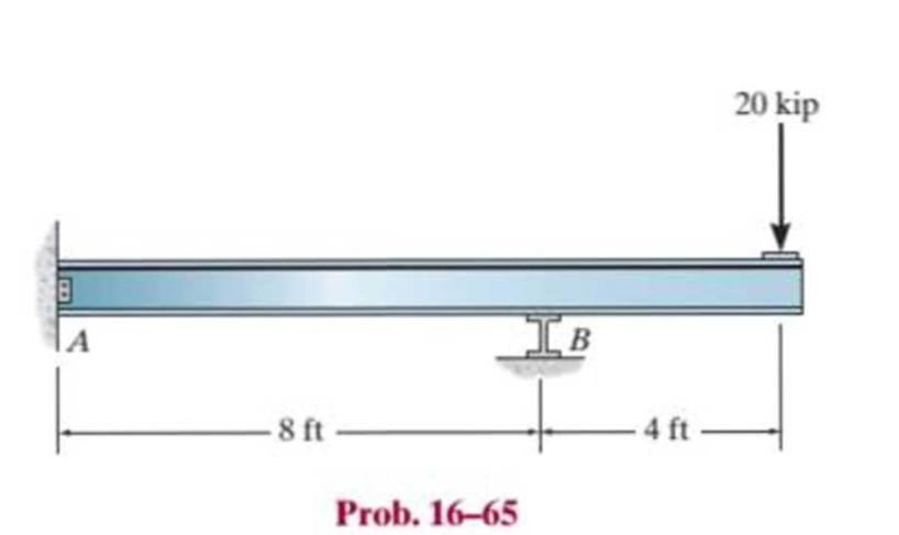
The beam is used to support the 20-kip load. Determine the reactions at the supports. Assume A is fixed and B is a roller.
Expert Solution & Answer
Want to see the full answer?
Check out a sample textbook solution
Students have asked these similar questions
Draw the free body diagram. Determine the reactions on the supports.
The fixed supported beam AB is strengthened using the simply supported beam CD and the roller at F which is set in place just before application of the load P. Determine the reactions at the supports if EI is constant.
Determine the support reactions
Chapter 16 Solutions
Statics and Mechanics of Materials (5th Edition)
Ch. 16.2 - In each ease, determine the internal bending...Ch. 16.2 - Prob. 1FPCh. 16.2 - Determine the slope and deflection of end A of the...Ch. 16.2 - Prob. 3FPCh. 16.2 - Prob. 4FPCh. 16.2 - Determine the maximum deflection of the simply...Ch. 16.2 - Prob. 6FPCh. 16.2 - An L2 steel strap having a thickness of 0.125 in....Ch. 16.2 - The L2 steel blade of the band saw wraps around...Ch. 16.2 - A picture is taken of a man performing a pole...
Ch. 16.2 - Determine the equation of the elastic curve for...Ch. 16.2 - Determine the deflection of end C of the...Ch. 16.2 - Prob. 6PCh. 16.2 - The A-36 steel beam has a depth of 10 in. and is...Ch. 16.2 - Prob. 8PCh. 16.2 - Determine the equations of the elastic curve for...Ch. 16.2 - Determine the equations of the elastic curve using...Ch. 16.2 - Determine the equations of the elastic curve using...Ch. 16.2 - Prob. 12PCh. 16.2 - Determine the maximum deflection of the beam and...Ch. 16.2 - The simply supported shaft has a moment of inertia...Ch. 16.2 - A torque wrench is used to tighten the nut on a...Ch. 16.2 - The pipe can be assumed roller supported at its...Ch. 16.2 - Determine the equations of the elastic curve for...Ch. 16.2 - The bar is supported by a roller constraint at B,...Ch. 16.2 - The bar is supported by a roller constraint at B,...Ch. 16.2 - Determine the equations of the elastic curve using...Ch. 16.2 - Prob. 21PCh. 16.2 - Determine the elastic curve for the cantilevered...Ch. 16.2 - Prob. 23PCh. 16.2 - Prob. 24PCh. 16.2 - The floor beam of the airplane is subjected to the...Ch. 16.2 - Determine the maximum deflection of the simply...Ch. 16.2 - The beam is made of a material having a specific...Ch. 16.2 - Determine the slope at end B and the maximum...Ch. 16.2 - Prob. 29PCh. 16.2 - Determine the equations of the elastic curve using...Ch. 16.3 - The shaft is supported at A by a journal bearing...Ch. 16.3 - The shaft supports the two pulley loads shown....Ch. 16.3 - Prob. 33PCh. 16.3 - Prob. 34PCh. 16.3 - The beam is subjected to the load shown. Determine...Ch. 16.3 - Prob. 36PCh. 16.3 - Determine the equation of the elastic curve and...Ch. 16.3 - Prob. 38PCh. 16.3 - Prob. 39PCh. 16.3 - Determine the slope at A and the deflection of end...Ch. 16.3 - Determine the maximum deflection in region AB of...Ch. 16.3 - Prob. 42PCh. 16.3 - Prob. 43PCh. 16.3 - Prob. 44PCh. 16.4 - The W10 15 cantilevered beam is made of A-36...Ch. 16.4 - The W10 15 cantilevered beam is made of A-36...Ch. 16.4 - The W14 43 simply supported beam is made of A992...Ch. 16.4 - The W14 43 simply supported beam is made of A992...Ch. 16.4 - The W14 43 simply supported beam is made of A-36...Ch. 16.4 - The W14 43 simply supported beam is made of A-36...Ch. 16.4 - The W8 48 cantilevered beam is made of A-36 steel...Ch. 16.4 - The beam supports the loading shown. Code...Ch. 16.4 - Prob. 53PCh. 16.4 - The W8 48 cantilevered beam is made of A-36 steel...Ch. 16.4 - Prob. 55PCh. 16.4 - Prob. 56PCh. 16.4 - Prob. 57PCh. 16.4 - The assembly consists of a cantilevered beam CB...Ch. 16.4 - Prob. 59PCh. 16.4 - Prob. 60PCh. 16.5 - Determine the reactions at the fixed support A and...Ch. 16.5 - Prob. 8FPCh. 16.5 - Determine the reactions at the fixed support A and...Ch. 16.5 - Prob. 10FPCh. 16.5 - Prob. 11FPCh. 16.5 - Prob. 12FPCh. 16.5 - Prob. 61PCh. 16.5 - Determine the reactions at the supports, then draw...Ch. 16.5 - Determine the reactions at the supports, then draw...Ch. 16.5 - Prob. 64PCh. 16.5 - The beam is used to support the 20-kip load....Ch. 16.5 - Prob. 66PCh. 16.5 - Determine the reactions at the supports A and B....Ch. 16.5 - Before the uniform distributed load is applied to...Ch. 16.5 - Prob. 69PCh. 16.5 - Prob. 70PCh. 16.5 - The beam is supported by the bolted supports at...Ch. 16.5 - Prob. 72PCh. 16.5 - Prob. 73PCh. 16 - Prob. 1RPCh. 16 - Draw the bending-moment diagram for the shaft and...Ch. 16 - Prob. 3RPCh. 16 - Determine the equations of the elastic curve for...Ch. 16 - Determine the maximum deflection between the...Ch. 16 - Prob. 6RPCh. 16 - The framework consists of two A-36 steel...Ch. 16 - Prob. 8RPCh. 16 - Using the method of superposition, determine the...
Knowledge Booster


Learn more about
Need a deep-dive on the concept behind this application? Look no further. Learn more about this topic, mechanical-engineering and related others by exploring similar questions and additional content below.Similar questions
- The beam is subjected to applied loads as shown. Determine the reactions at the supports. Determine the reactions at the supports. (Check all correct answers)arrow_forwardDetermine the reactions at the supports. Assume A and D are pins. EI is constant.arrow_forwardDetermine the magnitude of the reaction at support A, in kip. If: P = 276 lb, h = 14 in., A = 25 in. b = 9 in.arrow_forward
- The frame is loaded with the 800 N force as shownin the figure. Determine the reactions in the pins A,B and C.arrow_forwardDetermine the reactions at the supports. Assume A and B are pins. EI is constant.arrow_forward0.8 m 0.8 m 800 N 600 N B 0.4 m 0.4 m y A bent rod is supported by the roller at B, and the smooth collar at A. Find the reactions at all the supports for the loading shown.arrow_forward
- Find the reactions at the hinge support at A and roller support at D of the truss shown. P=200N.arrow_forwardDetermine the reactions at the supports.arrow_forwardThe compound beam is fixed at E and supported by rollers at A and B. Determine the reactions at these supports. There are pins at C and D. 800 lb --5ft+ 1200 lb C 600 lb 10 ft 5 ft 4 ft 6 ft D E -5 ft-arrow_forward
arrow_back_ios
SEE MORE QUESTIONS
arrow_forward_ios
Recommended textbooks for you
 Elements Of ElectromagneticsMechanical EngineeringISBN:9780190698614Author:Sadiku, Matthew N. O.Publisher:Oxford University Press
 Mechanics of Materials (10th Edition)Mechanical EngineeringISBN:9780134319650Author:Russell C. HibbelerPublisher:PEARSON
 Thermodynamics: An Engineering ApproachMechanical EngineeringISBN:9781259822674Author:Yunus A. Cengel Dr., Michael A. BolesPublisher:McGraw-Hill Education
 Control Systems EngineeringMechanical EngineeringISBN:9781118170519Author:Norman S. NisePublisher:WILEY
 Mechanics of Materials (MindTap Course List)Mechanical EngineeringISBN:9781337093347Author:Barry J. Goodno, James M. GerePublisher:Cengage Learning
 Engineering Mechanics: StaticsMechanical EngineeringISBN:9781118807330Author:James L. Meriam, L. G. Kraige, J. N. BoltonPublisher:WILEY
Elements Of Electromagnetics
Mechanical Engineering
ISBN:9780190698614
Author:Sadiku, Matthew N. O.
Publisher:Oxford University Press
Mechanics of Materials (10th Edition)
Mechanical Engineering
ISBN:9780134319650
Author:Russell C. Hibbeler
Publisher:PEARSON
Thermodynamics: An Engineering Approach
Mechanical Engineering
ISBN:9781259822674
Author:Yunus A. Cengel Dr., Michael A. Boles
Publisher:McGraw-Hill Education
Control Systems Engineering
Mechanical Engineering
ISBN:9781118170519
Author:Norman S. Nise
Publisher:WILEY
Mechanics of Materials (MindTap Course List)
Mechanical Engineering
ISBN:9781337093347
Author:Barry J. Goodno, James M. Gere
Publisher:Cengage Learning
Engineering Mechanics: Statics
Mechanical Engineering
ISBN:9781118807330
Author:James L. Meriam, L. G. Kraige, J. N. Bolton
Publisher:WILEY
BEARINGS BASICS and Bearing Life for Mechanical Design in 10 Minutes!; Author: Less Boring Lectures;https://www.youtube.com/watch?v=aU4CVZo3wgk;License: Standard Youtube License